|
The following are news releases regarding software and development
capabilities related to the 1802.
|
SOFTWARE DEFINED RADIO PIONEER
|
|
From QST magazine, April 2017, p87:
Ulrich Rohde, N1UL, recognized for pioneering work on SDR
While working under a U.S. Department of Defense contract at RCA in 1982,
Rohde's department developed the first Software Defined Radio, which used the COSMAC
(Complementary Symmetry Monolithic Array Computer) chip. Introduced by
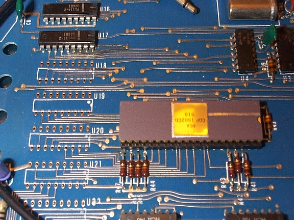
RCA in early 1976, the RCA CDP1802 eight-bit CMOS microprocessor - a
40-pin LSI integrated circuit chip - was the company's first single-chip
microprocessor. Rohde was among the first to present publicly on this
topic with his February 1984 talk, "Digital HF Radio: A Sampling of
Techniques" at the Third International Conference on HF Communication
Systems and Techniques in London.
|
|
RCA EXPANDS MICROPROCESSOR AIDS
|
|
From UK magazine Microprocessors, volume 1 number 2, December 1976:
RCA Solid State Europe entered the microprocessor market early in 1975
with the announcement of COSMAC, initially conceived as a two-chip
general-purpose computing element aimed at inexpensive digital systems.
The 8-bit microprocessor architecture is designed to give great
flexibility, simplicity of programming and inexpensive interfacing, while
the instruction set and input/output interface are designed to minimize
memory requirements and system complexity. The microprocessor uses
complementary MOS technology, characterized by very low power consumption,
high noise immunity and tolerance to supply-voltage variations.
In November 1975, RCA announced the full commercial availability of a
microprocessor family, encompassing the existing COSMAC (then designated
CDP1801, but now replaced by the single-chip CDP1802).
A recent development from RCA Solid State, the CDP1802 is a logical
extension of the earlier products. Essentially using the same architecture
as the initial COSMAC device, it is a single-chip microprocessor using
self-aligned silicon-gate C-MOS technology. The CDP1802 is accompanied by
a series of peripheral and interface circuits, including ROMs and RAMs
using silicon-gate and silicon-on-sapphire technology, plus input and
output circuits.
The main features of the CDP1802 architecture are: simple architecture
for ease of understanding by the user; the concept of separating
addresses from instructions placing them instead into an array of
internal registers and thus allowing many compact one-byte instructions;
powerful built-in interface capabilities.
|
|
From the February 1977 issue of Radio-Electronics magazine:
Microprocessors are available in different
technologies -- PMOS, NMOS, bipolar, and CMOS. CMOS has the distinct
advantages of low power dissipation and wide-temperature operation. RCA's
1801 microprocessor was a two-unit deal that was relatively slow and
expensive. Started out at $200, the price of the pair dropped into
the still unattractive $50 range.
But they haven't been sleeping! Just
announced is a single-package CDP1802 COSMAC microprocessor that is a
dramatic improvement over the earlier version. New instruction repertoire
has been added, cost is competitive, down to under $30 levels, and
the execution speed of single-cycle instructions is down to 2.5
microseconds. Standard aluminum gate construction has been supplanted
with a self-aligned silicon-gate process that cuts down chip area
and increases yield.
RCA's new 230 x 180-mil μP retains the unique
architecture of the older 1801 design. Programs written for the earlier
circuit will run without change on the new one. It is built with a new
C2L closed-COS/MOS logic. Source connections are common and
separate contacts are not needed. Guardbands to
prevent parasitic action are not needed, yet the CDP1802D can operate
at full supply range of 3-12 volts.
The CDP1802 block diagram in Fig. 2
shows an 8-bit address bus MA0 through MA7. The bus is time-multiplexed
to 16 bits. Storing the first 8 bits in an external latch gives 65K of
memory addressing capability. Sixteen general-purpose registers distinguish
the RCA approach from contemporary processors. Each register
is 16 bits long, which adds up to 32 8-bit bytes or a total of 256
read-write scratchpad bits. By loading these registers with frequently
used addresses and data, efficient programming code can he written. Single-byte
instructions replace multiple-byte main memory addressing
operations in other schemes.
Any register can he designated as the
program counter or data pointer. One of three 4-bit registers selects
the particular one of the 24 scratchpad registers.
Many of the memory
and register instructions include a 4-hit operand that is stored in
the N register. The most significant 4 bits of the instruction is the
operation code and is stored in the 4 bit I register. For example, the
instruction format IN is an increment register operation. To increment
register 5 by one, the instructions would be 15 in hex or 00010101 in
binary. Binary number 0001 would he stored in the I register and 0101
in the N register. The control logic decodes the op-code and sends out
signals to direct the N register to select register 5 in the array. The
control logic then causes the addressed register to he incremented by
one by the incr decr block in Fig. 2.
In instructions where register addressing is not used, all 8 bits are
interpreted by the control logic and none of the scratchpad registers
are selected.
The 4-bit P register decides which of the 16 is to be
used as the program counter. The program counter holds the address of
the program stored in memory and is incremented sequentially to fetch
successive program steps.
The 4-bit X register picks the register to be referenced by arithmetic
and logic operations.
Interruptions in program executions by peripherals
such as terminals and disk memories are standard computer procedures. The
8-bit T register is used to hold the X and P register contents and
store them in a single memory-location. After servicing the inter-
rupting device with a special program routine, the T register is used
to reset X and P to their original values so the main program can
continue from where it left off.
The 8-bit D register is the μP
accumulator. Data is transferred in either direction between the D
and scratchpad registers. Since the general registers are twice the
length of the D register, either the low or high byte can he loaded by
separate instructions.
Data transferred to and from memory must pass
through the accumulator and is handled by a series of eight memory
reference instructions. The instructions use either the X or P
registers as operands. These pointers will either stay fixed or will be
automatically incremented by the choice of instruction.
Arithmetic and
logic operations take place between memory and the D accumulator, governed
by an extensive series of instructions. The 1802 has a number of
new immediate instructions that are two bytes in length. These load
constants or use them as other operands. Immediate means the constant
is stored in the second byte of the instruction. This is very useful
when setting up indexes or initial memory pointers, which can then be
incremented or decremented by the program.
At the heart of many machine-language routines are the branch instructions,
and a large assortment
will save programming code. The 1802 selection includes two-byte short
branches where the second byte is the address that replaces the low
program counter byte. Jumps over a 28, 256 word total range on the same
memory page use these instructions. New to the 1802 are long branches
that are three-bytes and allow jumps to any location in memory. The
high and low address bytes to be inserted into the program counter
are in the second and third instruction words. Except for the
unconditional branches, the decision to jump or not is based on the state of
the D register, and the DF, Q, and EF flags. DF, the data flag, is a one-bit
ALU carry flip-flop. Q is a program controlled flag, and EF1 through
EF4 are a group of flags controlled by peripherals.
Short and long skip
instructions are similar to the branches in that they are executed in
response to the same flag conditions, but their action is limited to the
skipping of either one or two steps in the program. They are single-byte
instructions that are very efficient in terms of memory space.
The ten
control instructions include the stack return and idle operations. The
remaining group are the output instructions that route data from the
registers pointed to by X to the output data bus or from the input data
bus. During input-output operations, the 4-bit N register is set to
a value between 1 and 7 and used to select the peripheral device.
The unit price of the 4-6-volt 5-μs CDP1802D is $29.50. The 3-12 volt full
speed CDP1802CD is $43.50. Information is available from RCA Solid
State Division, Route 202, Somerville, NJ 08876.
|
|
[ From the August 1977 issue of Radio-Electronics magazine. ]
 Infinite, Inc., takes two different approaches to the microcomputer
learning/development system. First, they produce a training-and-use
package that leads the uninitiated unfalteringly into the world of the
computer. For example, their model UCI800 microcomputer is a completely
assembled and self-contained microcomputer system. It avoids construction
pitfalls and the futile troubleshooting that often follows. To determine
whether a problem is in the microprocessor IC or elsewhere can be very
difficult without the necessary skill and sophisticated equipment.
Infinite, Inc., takes two different approaches to the microcomputer
learning/development system. First, they produce a training-and-use
package that leads the uninitiated unfalteringly into the world of the
computer. For example, their model UCI800 microcomputer is a completely
assembled and self-contained microcomputer system. It avoids construction
pitfalls and the futile troubleshooting that often follows. To determine
whether a problem is in the microprocessor IC or elsewhere can be very
difficult without the necessary skill and sophisticated equipment.
On the other hand, Infinite has also developed the model UC1800HK Hobbyist
Kit for the experienced kit builder. The kit contains only special
components that are not widely available.
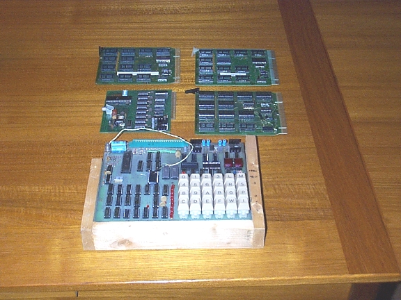
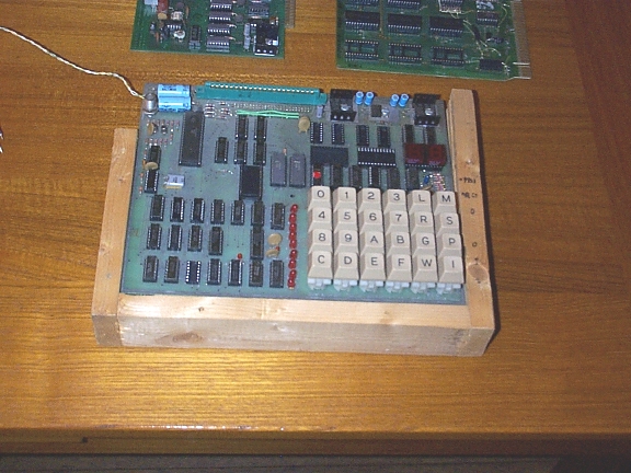
The UC1800 is a completely
assembled microcomputer system built around the RCA COSMAC model CDP1802
microprocessor. Four printed-circuit boards are mounted in a console-type
cabinet that resembles a desk-type calculator.
The central
processor board holds the CPU IC, the CPU control logic, 256 words of NMOS
RAM and the 5-volt power supply (except the power transformer mounted
separately in the cabinet). The CPU board has a 72-pin gold-plated edge
connector for system expansion. The readout board has four 7-segment
LED displays and the associated decoder-driver IC's. Two displays
function as the address readout, and the other two as the instruction
and input/output readouts. The LED's display the hexadecimal (base 16)
representation of the computer's binary numbers. After 0 through 9, A, C,
E and F are displayed and "b" and "d", using the available segments. The
board contains its own 5-volt regulator IC to supply the substantial
400-mA current drain.
The third board is the switch-control module
that interfaces with the six control switches. They are RESET, SINGLE
STEP, START/EFI, POWER, MODE and SINGLE STEP/ENTER.
The board has outputs that connect to the
EF1,
CLR,
WAIT,
and
DMA IN,
terminals on the microprocessor IC.
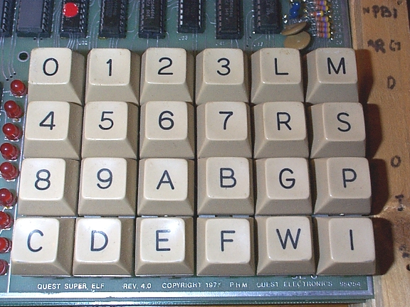
The keyboard module holds the 16
hexadecimal keys and the necessary debouncing and decoding components. Two
LED's indicate whether the most or least significant of the two hex
digits in each word is ready for loading.
To load a program, set the
MODE switch to LOAD, then RESET, enter the first word, press ENTER
and continue. The loading starts at 00 and proceeds sequentially. If
you make a mistake along the way, you must either start all over or
enter a short program that allows you to change a particular memory
location.
After the program is loaded, the MODE switch is then placed
in the RUN position and the SINGLE STEP switch can be turned either
ON or OFF. With the switch OFF, the computer executes the program
automatically. With the switch ON, the computer executes a single
instruction for each push of the SINGLE STEP/ENTER button. The START
switch shares the EFI input function that you can use to interact with
your program. Input and output instructions permit you to enter data from
the keyboard and readout into the two LED's.
The POWER switch maintains
power to the memory only in the STANDBY position to preserve the program
with minimum power consumption. You can also purchase a nickel-cadmium
battery and charger to keep the memory alive for about four hours after
loss of primary AC power.
The DMA (Direct Memory Access) design of the
model CDP1802 facilitates program loading without using a ROM utility
program. There is an advantage in not requiring this extra component,
but it does make the system cumbersome to use.
Infinite addresses this
problem by including a listing and instruction for using KEYBUG as part
of the UCI800 package. This program takes one-half of the available 256
memory words, and of course it must be successfully loaded starting at
address 00.
KEYBUG has five commands that help in loading, examining and
changing memory contents. After the program is loaded, a RESET-START
sequence gives control to KEYBUG, which is acknowledged by displaying
"db" (debug).
The DC command will display the contents of a single memory
location. Press the D and the C followed by EF1, which serves to enter the
command. Then key in the address of the location to be displayed and press
EF1 again. The program responds by displaying the memory contents. The
CC command changes the contents of memory. After the command and
the memory-location address are entered, the new contents are keyed in
and EF1 depressed. Since only a single memory location is accessed by
the DC and CC commands, the system can return to KEYBUG automatically
and be ready for a new command.
To examine a series of memory locations
without entering memory addresses sequentially use the FD (forward
display) command. The computer displays the address and its contents;
then increments the address and displays its contents each time EF1 is
pressed. Similarly, the FC forward change command sequentially loads the
memory by pressing the EF1 switch after each data entry. These last two
commands are self-looping; the only way to exit the loop so that a new
command can be executed is to reset and restart KEYBUG.
The remaining
command is EE for execute. The EE command is keyed in, EF1 pressed,
the program-starting address entered and EF1 pushed again. Because
KEYBUG starts at 00 and a program cannot be written there, EE is the
only way to activate a program.
To debug your program, set breakpoints
by inserting a branch to 00; this causes a "db" readout when KEYBUG is
reached. You can then examine memory to see what has taken place so far. A
more sophisticated approach would be to examine the processor registers
when the breakpoint is reached, restarting the program and continuing
to the next breakpoint.
So far KEYBUG is not available on PROM or
ROM and must be loaded manually into RAM. A defective user program may
destroy the utility program. This happened several times while I was
experimenting with some simple programs. Some wipeouts did not
completely annihilate the system, and it was possible to use KEYBUG
to find the destroyed memory locations and restore the full capabili-
ties. Some wipeouts were total.
The Infinite computer is available in four
versions: The completely assembled and documented UC1800 package includes
computer, instruction manual, RCA MPM-201A CDP1802 Users Manual,
KEYBUG program and Cardiac. Cardiac (Cardboard Illustrative Aid to Com-
putation) was developed by Bell Telephone Laboratories to simulate the
operation of a simple computer. Cardboard slides simulate the instruction
decoding, and calculation is done with pencil and paper. The package is
priced at $495, plus $8 for shipping and handling. Option 001 is the
battery backup and recharger and sells for $22.50. Option 002 enables
you to use the microcomputer with either 120 or 230 VAC 50-500-Hz
input power and costs $15.
The UC1800 kit includes everything but the
cabinet and power cord. The four modules are factory-assembled and burned-in.
This version sells for $389, plus $4 for shipping and handling.
The economy model (model UC1800HK) contains four unwired boards, keyboard,
1802 CPU, readouts, cable and Users Manual. It is priced at $129.95,
plus $2 for shipping and handling. If you already have a CDP 1802,
Option 003 subtracts $18 from the price.
|
|
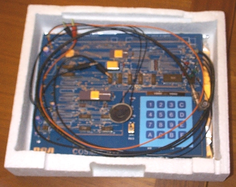
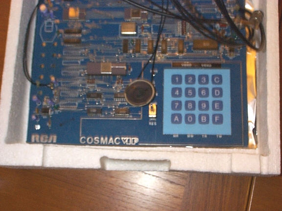
[ From the May 1978 issue of Radio-Electronics magazine. ]
 The RCA Video Interface Processor is a hobbyist
microcomputer with a graphic video output. As soon as it is assembled
and operational, you become acquainted with the system by loading
and running an assortment of video games, including "Kaleidoscope" and
(my favorite) "Armored Vehicle Clash." After you gain this initial
familiarity and have some fun, you can graduate to writing 1802 machine
language and CHIP-8 programs.
The RCA Video Interface Processor is a hobbyist
microcomputer with a graphic video output. As soon as it is assembled
and operational, you become acquainted with the system by loading
and running an assortment of video games, including "Kaleidoscope" and
(my favorite) "Armored Vehicle Clash." After you gain this initial
familiarity and have some fun, you can graduate to writing 1802 machine
language and CHIP-8 programs.
The VIP is constructed on a single 8 1/2 X 11-inch PC board that holds
the CDP1802 microprocessor, 2048 words
of user RAM, a 512-word ROM-based operating system, a 3.521280-MHz
crystal oscillator, a video display generator IC, a cassette recorder
interface and various system related IC's. A 5-volt, 600-mA power-supply
module is part of the package. On-board memory can be increased
to 4096 words (a higher current supply may be needed), and parallel I/O
ports can be added by filling wired, empty IC positions. Standard 44-pin
connectors can be used to expand up to 32,000 memory bytes, and beyond the
19-line on-board I/O limitation.
Programs, data and system control commands
are entered through a 16-key hexadecimal keypad. Depressing a
key switch on the keyboard operates the Q light, affects the on-screen
display and generates an audio tone (the speaker is not included). The
uppermost 256-byte portion of memory is displayed in a format that is
64 bits horizontal by 32 bits vertical. The video output is monochrome
and noninterlaced, and must be connected to a video monitor, the video
circuits of a TV receiver, or an external RF modulator for hookup to a
TV antenna terminals. User programs are started at address 0000 by
flipping the reset toggle switch from RES to RUN. To access the 512-word
operating system at address 8000, key C is held while the reset switch
is flipped.
The operating system has four functions - memory write,
memory read, tape write and tape read. When memory contents are entered
and checked, the address and contents are displayed simultaneously at the
bottom of the TV screen, so you can keep track of what you are doing. The
video format can be expanded
to 64 X 64 bits or 64 X 128 bits for higher resolution by writing
your own video refresh interrupt routine in machine language. Video
format expansion uses more memory for the display (512 bytes or 1024
bytes). Using the video display slows down the processor because of
the time it spends translating memory contents into a video display
pattern. The operating system saves the processor registers on the
last page of memory for debugging programs.
The CHIP-8 interpreter
is a 5I2-byte program that you must load manually, or from tape,
into locations 0-01FF. CHIP-8 user programs, such as games, are then
loaded starting at 0200. The language is a series of 31 two-byte
instructions that let you control up to 15 variables, run a timer,
display patterns, generate a variable-duration audio-output tone,
convert binary to decimal, obtain random numbers and perform skips and
subroutine jumps. You can create all kinds of static and moving displays
with relatively few instructions. The CHIP-8 interpreter should be
stored on cassette tape to save reloading and checking each time you
want to use it.
A VIP operating manual, the MPM-201 1802 microprocessor
manual, and data sheets describing the ROM, video display IC and 1802
microprocessor are included. The VIP manual includes all the details,
but a beginning computer hobbyist will find a reference book or two
helpful. Twenty video games are listed, plus some short
"getting-started" programs.
Kit assembly requires good soldering technique since
a single short between the necessarily close PC traces keeps the unit
from creating its pretty pictures. While the VIP is basically designed to
be used for fun, it can be expanded to perform useful control and calculation
work.
After I resolved a couple of self-inflicted assembly errors,
the system performed flawlessly. Programing mistakes did have the
annoying habit of wiping out CHIP-8, but shifting to the tape cassette
mode of operation made recovery easy. I used both an inexpensive time-worn
audio cassette recorder and a better-grade Heathkit tape
deck. The tape deck loaded programs successively nine times out of 10,
but the less expensive recorder performed only once out of every three
times.
The model CDPI8S022 VIP Kit is priced at $275. An order form is
available from RCA Solid State Division, Box 3200, Somerville, NJ 08876.
|
|
RCA CDP18S020 COSMAC Evaluation Kit
|
|
[ From the July 1979 issue of Radio-Electronics magazine. ]
 The RCA 1800 series COSMAC microprocessor and its associated family of
devices have a couple of unique characteristics. First, because they
are COS/MOS devices, the power drain is low, starting at the milliwatt
level. Single-IC standby memory power is also in the low milliwatt
range.
The RCA 1800 series COSMAC microprocessor and its associated family of
devices have a couple of unique characteristics. First, because they
are COS/MOS devices, the power drain is low, starting at the milliwatt
level. Single-IC standby memory power is also in the low milliwatt
range.
Second, the 1800 family tolerates an unusually wide power supply
range - 3 to 12 volts for
the CDP1802 with a 3.2-MHz clock. And the operating temperature range
for the full-speed processor and certain memory products covers the full
-55 to 125°C temperature range. This is important if your
microprocessor-controlled gadget will form part of an automotive system.
The processor
instruction set is based on a 16- X 16-bit scratch-pad organization that
provides good programming flexibility.
The RCA CDP18S020 Evaluation Kit
is a relatively inexpensive tool with which to learn about the RCA 1802,
prototype a microcomputer system, or develop software. A 20-mA loop or
RS232C terminal is normally required to use the Evaluation Kit, although a
simple keyboard or switch interface can be designed. Board dimensions are
14 X 9.7 inches, including fully decoded prewired locations for expansion
to 4096 bytes of random-access memory (RAM), and a 6- X 4-inch user
area wired to accept standard DIP packages.
Three edge connectors provide
access to the microprocessor pins and the user input-output (I /O) area,
and connect to external power sources and peripheral devices. The kit
comes with a 2-MHz crystal which, for the 16- and 24-clock-period
instructions, calculates to 8-µs or 12-µs execution times. A
6.4-MHz oscillator reduces these values to 2.5 and 3.75 µs.
A 512-byte ROM is assigned address space from 8000 to 81FF and permanently stores
the UT4 monitor program. A 32-word RAM starting at 8C00 is used by
the utility program to store register contents. Two supplied RAM IC's
fit into the first two locations in the 4K memory area for an initial
256-word user programming space.
System operation is controlled by
three pushbuttons and a toggle switch. The RESET pushbutton intializes
the CPU and control logic: RUN U (Run Utility) gives control to the ROM
monitor program by starting execution at 8000. The RUN P (Run Program)
pushbutton starts program execution at 0000, where the first user's
program instruction is usually entered. The CONTINUOUS/STEP toggle
switch lets the user choose between the normal clocked mode or
single-cycle operation, where individual program steps can be dissected down
to 2 machine or 3 machine cycles-per-instruction.
A series of 29 LED's
display the status of the 16-bit memory address bus, the 8-bit data bus,
the SO and SI processor state codes, the
CLEAR
and
WAIT
control signals,
and the processor's Q flip-flop. Bidirectional communications to a
data terminal are provided by interface circuits that use the Q flip-flop
for output and the
EF4
flag to input the serial data. Detailed
instructions show how to hook up to current loop terminals such as
Teletypes, and to EIA RS232C interfaces such as Texas Instruments'
Silent 700 terminal. Parallel 8 -bit input and output ports are included
in the kit.
External power supplies are required - of 5
volts at 600 mA, or 10 volts at 200 mA with a separate 5-volt 400-mA
supply for the LED's.
Assembly
Kit assembly was pleasantly uneventful
with the help of a high-quality, double-sided PC board with plated-through
holes. Close PC runs are necessity on microcomputer boards, and
careful soldering and inspection techniques are a must. Sockets are
provided for the microprocessor and utility ROM IC's, but, as always,
I recommend using additional sockets or Molex pins to mount some or all
of the remaining 22 circuits.
The checkout procedures consists of measuring
the resistance of the supply input leads, and loading and executing
a four-instruction program that sets and resets flip-flop Q.
Figure 1 demonstrates the writing of data to memory, the reading of data from
memory, and starting programs. The UT4 program recognizes three commands
corresponding to each of these functions.
After pressing the RESET and RUN
U push-buttons, type either a carriage return or a line feed depending
on whether your terminal is connected for full-duplex or half-duplex
operation. Full-duplex operation requires the computer to echo back
characters typed on the keyboard to the printer, since the two terminal
functions are completely isolated. Based on the first character typed,
the utility program sets up to echo or not, and calculates the bit
timing necessary to talk and listen to the terminal.
Figure 1 shows how
the three-command repertoire works. First, you enter a program either
from the keyboard or from punched paper or magnetic tape. The command
!M is the write-memory command, which is immediately followed by the
address where the input should be entered - in this case, 0 or 0000. The
space after the 0 separates the address from the data. Next, the program
instructions or data are entered in hexadecimal format, with each two
characters accounting for a single memory word. In hexadecimal or base
16 format, additional symbols are needed for numbers between 10 to
15. Letters from A through F are used to represent 10 through 15 with a
single symbol.
Spaces can be imbedded between words if desired. At the end
of the line, you have a number of choices. In Fig. 1 the first line is
terminated by a semicolon. This told the machine I wasn't finished yet,
and that I will give a new address and more input. Everything else was
ignored until the next hexadecimal
digit. I then added an extra line feed to make the printout more
legible. On the second line I started to type 10 but decided I really
wanted to enter more data starting at address 20. The system (being
forgiving) only pays attention to the last four numbers entered, so I
typed 0020 (or I could have typed 020 since one 0 was already there from
the 10). I then hit the space bar and typed in the data.
This time I hit
a comma at the end of the line that told the machine I still had more data
to enter but wanted to continue on the next line. With the comma the data
continues in sequence and a new address is not given. At the end of the
third line I decided to go back and fill in data starting at 000F; so
I used the semicolon again.
Finally, at the end of line 4, I simply used a
carriage return, indicating I was through, and the machine responded with
the prompt asterisk on the following line.
At this point, you're ready
to check by reading out memory contents with the ?M command. Again,
you use 0 as the starting address; however, the 30 is not data but
the number of words in hexadecimal format to be typed out - 3016 = 3
X 16 = 4810 words. The next three lines represent the response to that
command. The first four columns display the starting address for each
line followed by 16 words grouped by two's. The last byte on the 0000
line is the AF that I inserted at address 000F on line 4.
Note the format
that the machine uses to output memory contents. The first two lines
begin with addresses and end with semicolons, and the third line starts
with an address (0020) and ends with a carriage return. This allows the
data to be stored on tape in this format and then later be read back in
using the compatible !M command.
The next group of lines demonstrate a
memory dump of 1016 or 1610 words starting at 0020.
The UT4 monitor
program uses a 32-byte RAM starting at 8C00 to store the 16 scratch-pad
microprocessor registers. This feature is helpful in troubleshooting,
but care must be used since certain registers are modified by the
system. The program cannot be restarted from an intermediate point
after being interrupted by inserting an idle instruction unless the
registers are restored.
The next three lines in Fig. 1 show how the
register RAM is printed out with the ?M8C00 20 command. Characters RO
and R7 are displayed on the line prefixed by 8C00, and R8 through RF on
the line starting with 8C10.
Command $P starts program execution. If no
address is given, execution begins wherever the program counter is set,
usually at 0000. Otherwise, the program is started at the address typed
immediately after $P.
A large loose-leaf binder comes with the kit. It
includes detailed sections on kit assembly, design and operation of the
system, the utility program (including listing), application notes on I/O
and control, software and memory.
The CDP18S20 evaluation Kit is priced
at $249 and is available from RCA Solid State Division, Somerville,
NJ 08876, or from RCA Solid State distributors.
|
|
From UK magazine Microprocessors:
The CDS II development system for CDP1802 microprocessors includes a
19in rack-mountable chassis with printed-circuit backplane, internal
power supplies, clock and controls, a front panel with controls and
display, and seven plug-in printed-circuit modules including a central
processor, control, address-latch and bank-select, RAM and ROM
memories, I/O decode, and terminal interface. Seven spare memory
module positions and ten spare I/O positions are provided. Extra
memory or I/O modules are available as options.
The CDS II comes with both papertape and magnetic-tape cassette versions
of the resident editor and assembler programs which can be loaded into the
4 kbytes RAM supplied. A floppy disc option is also available. The
utility program provided allows the user to inspect and modify memory and
to start program execution at any location. It can also load programs,
dump memory, and interface terminals for serial ASCII data terminals. It
automatically adjusts to baud rates between 110 and 1200 operates in full
or half duplex mode (RCA Solid State Limited, Sunbury-on-Thames, Middx,
UK. Telephone Sunbury-on-Thames 85511).
|
|
TEKTRONIX SUPPORT FOR 1802
|
|
From UK magazine Microprocessors and Microsystems:
RCA's 1802 8-bit CMOS microprocessor is to be supported by the
Tektronix 8001/8002A microprocessor development lab. Because of its
CMOS characteristics, the 1802 is widely used in severe environments
and/or portable applications.
|
|
From UK magazine Microprocessors and Microsystems:
A resident utility program for RCA's 1802 microprocessor has been
developed by the Golden River Company. The program, GRUTIL,
will provide 1802 users with the capability to load a program from an
external source such as a Teletype keyboard, paper tape or a
timesharing system. The program runs directly on Golden River's
GR0430 low power SBC and on the MK4 control system.
By using one of four specified commands the user may interrogate
memory and punch a reloadable paper tape, enter data into memory or
load a program, transfer blocks of memory from one location to
another or proceed with program execution. GRUTIL will
detect bad syntax and data errors and allow the aborting of wrong
commands. The output may be terminated at any time by the user.
The program is available in ROM or PROM and can be contained in a
1k chip. Program size is less than 1024 bytes of CDP 1802 machine
code. Input may be either Teletype and paper tape or magnetic tape
and cassettes. Suitable terminations include ASR33, TI733,
TI 743 and VDUs at speeds between 10 and 960 cps.
(Golden River Co. Ltd., Telford Road, Bicester, Oxon, OX6 0UL, UK.
Tel: Bicester 44551)
|
|
From UK magazine Microprocessors and Microsystems:
Two software packages support the COSMAC CDP1800 microprocessor family.
Both systems, the RAL-II Level-II assembly language and the C-MAC
macroassembler, are designed to cut development time. The RAL-II
assembler, provided with the RCA's floppy-disk system, allows the
assembly of COSMAC Level-II assembly language. Use of RAL-II shortens
source code by about 35%, with the use of a class of special
'super-instructions'.
Also available with the floppy-disc system is the C-MAC macro-assembler,
which has macroinstruction definition, conditional assembly and
'program-build'.
A range of fixed-point and floating-point binary arithmetic subroutines
has also been made available. Among the packages is an implementation of
the fixed-point subroutine on a 1 kbyte ROM. The software includes 31
subroutines including register save and mathematical companion operations,
with arithmetic functions, format conversion and utility subroutines.
The roujtines are all in 16-bit 2's-complement format.
(RCA Limited/Solid State Europe, Sunbury-on-Thames, Middlesex,
Englanhd. Tel: Sunbury-on-Thames 85511. Telex: 24246).
|
|
From UK magazine Microprocessors and Microsystems:
A software package from RCA allows software development for 1802
microprocessor family to be carried out on the Intel MDS prototyping
systems. This crossassembler consists of a macro file designed to
run in conjunction with the Intel 8080/8085 macroassembler.
The crossassembler is designed so that the user writes his program in
1802 mnemonics, uses an MDS command to generate a suitable macrofile,
and then assembles his program in the normal way to generate 1802
machine code.
For program loading into the 1802-based prototype, the user can use
either an Intel EPROM programmer to develop the necessary firmware
or the RCA transcoding program to load the RAM of an RCA Micromonitor,
which can then be used for subsequent debugging.
(RCA Limited/Solid State Europe, Sunbury-on-Thames, Middlesex,
England. Tel: Sunbury-on-Thames 85511. Telex: 24246).
|
|
ALERNATIVE US COSMAC SUPPLY
|
|
From UK magazine Microprocessors and Microsystems, Volume 1 Number 6, August 1977:
RCA have just signed an agreement with Solid State Scientific Incorporated of
Montgomeryville, USA, which will provide the company with artwork and tooling
for the manufacture of the CDP 1802 8-bit CMOS CPU, the CDP 1822S 1-kbit
silicon-on-sapphire RAM, the CDP 1824 256-bit RAM, the CDP 1831 4-kbit ROM,
and the CDP 1852 8-bit I/O port.
SSS have been a large supplier of CMOS integrated circuits in the US since 1971 and
will provide a viable second-source for these devices.
|
|
From UK magazine Microprocessors and Microsystems, Volume 5 Number 1, January/February 1981:
True full-screen editing on an integral data terminal with CRT display is featured in the
COSMAC microprocessor development system, CDP18S008, from RCA Solid State for microprocessor
systems based on the RCA CDP1802 and CDP 1804/5 microprocessors. The development system
comprises VDU and data terminal with an ASCII keyboard with 72 standard keys and 14 special
function keys; a dual floppy disc drive; 60 kbyte of user-accessible static CMOS RAM; a CDOS
disc file-management and operating system; a new resident ASM8 macroassembler, editor and
utility program on floppy; a plugin MOPS-augmented Micro-monitor (in-circuit emulator) for
extensive online and offline debugging of both software and hardware; a builtin PROM programmer;
and a builtin printer interface for RCA's new matrix high speed printer, CDP 18S050.
In single quantities, the RCA COSMAC Development System IV CDP 18S008 is priced at
£s;7965.
(RCA Solid State Europe, Sunbury-on-Thames, Middlesex, TW16 7HW,
UK. Tel: Sunbury-on-Thames 85511).
|
|
 Although the 1802 is now more than 30 years old, it continues to
prove itself in many industrial and commercial applications.
A persistent rumor identifies it as the furthest microprocessor from Earth, having
been used on board the Voyager spacecraft. (Voyager 1 is now
the furthest human-made object from the Earth, at more than 100 A.U. distance.)
Certain versions of the chip were extremely resistant to cosmic ray upset,
making it well-suited for use in space. However, design work for the Voyager
and Viking series spacecraft began long before the 1802 was available;
instead they used custom-engineered computers. The Galileo spacecraft, however,
used several 1802 processors.
Although the 1802 is now more than 30 years old, it continues to
prove itself in many industrial and commercial applications.
A persistent rumor identifies it as the furthest microprocessor from Earth, having
been used on board the Voyager spacecraft. (Voyager 1 is now
the furthest human-made object from the Earth, at more than 100 A.U. distance.)
Certain versions of the chip were extremely resistant to cosmic ray upset,
making it well-suited for use in space. However, design work for the Voyager
and Viking series spacecraft began long before the 1802 was available;
instead they used custom-engineered computers. The Galileo spacecraft, however,
used several 1802 processors.
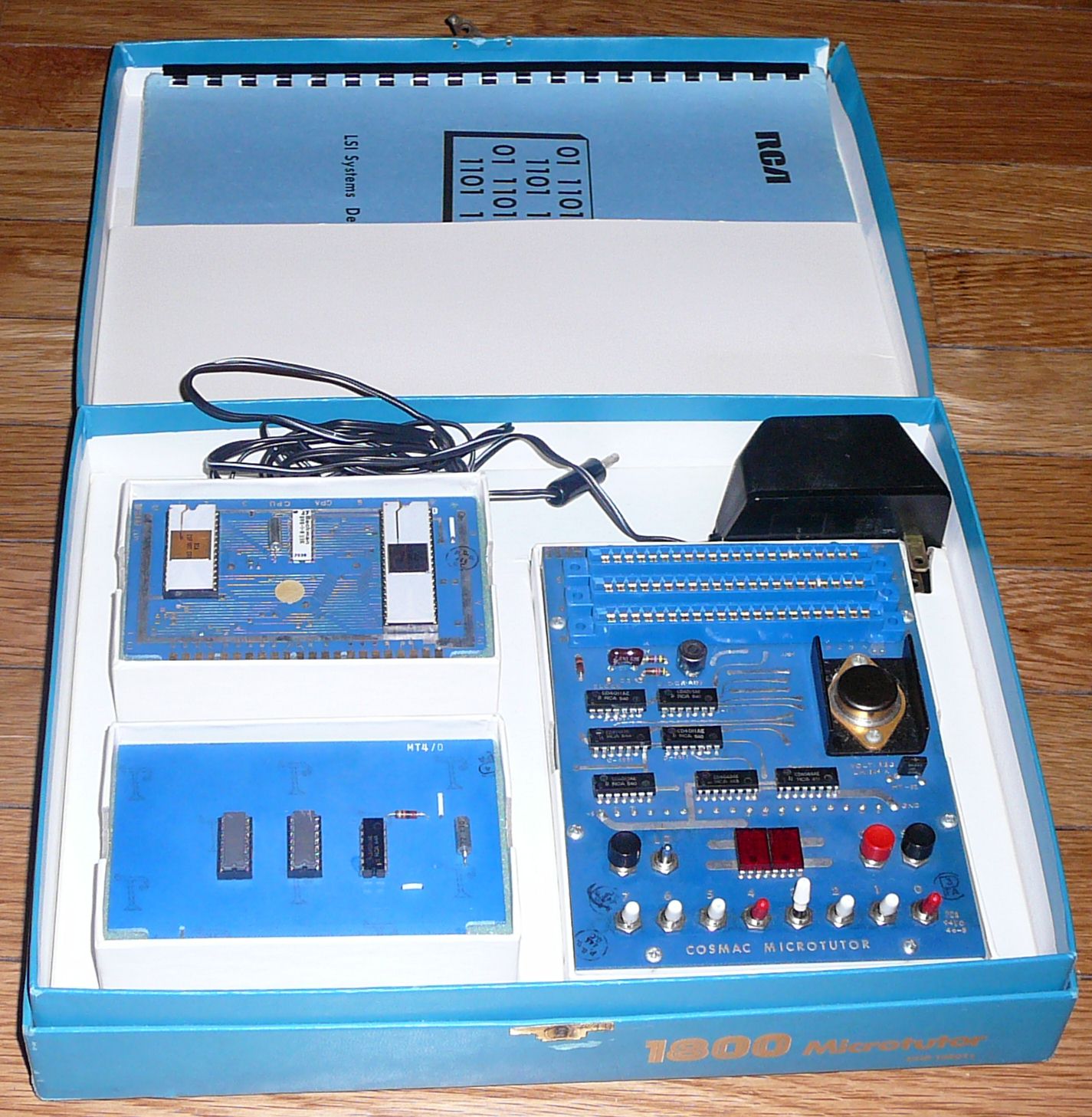
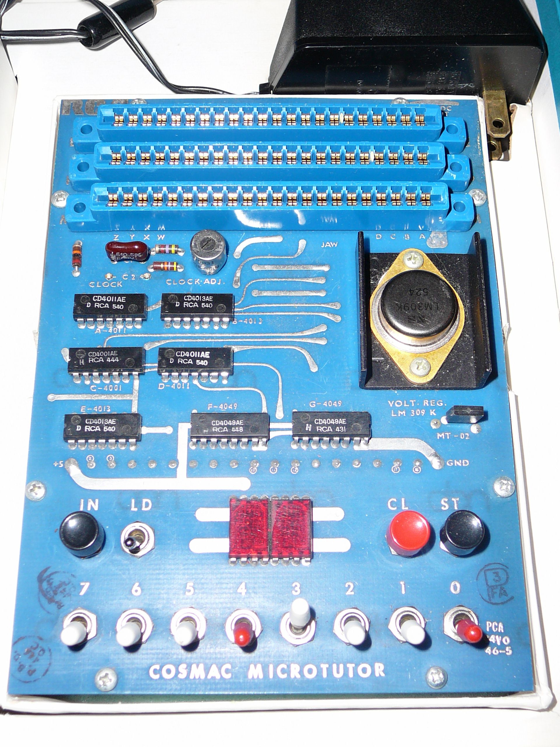
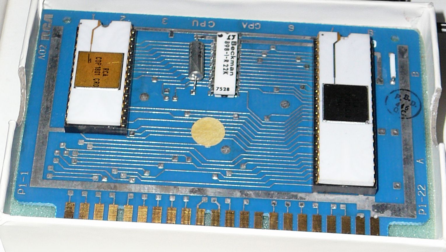
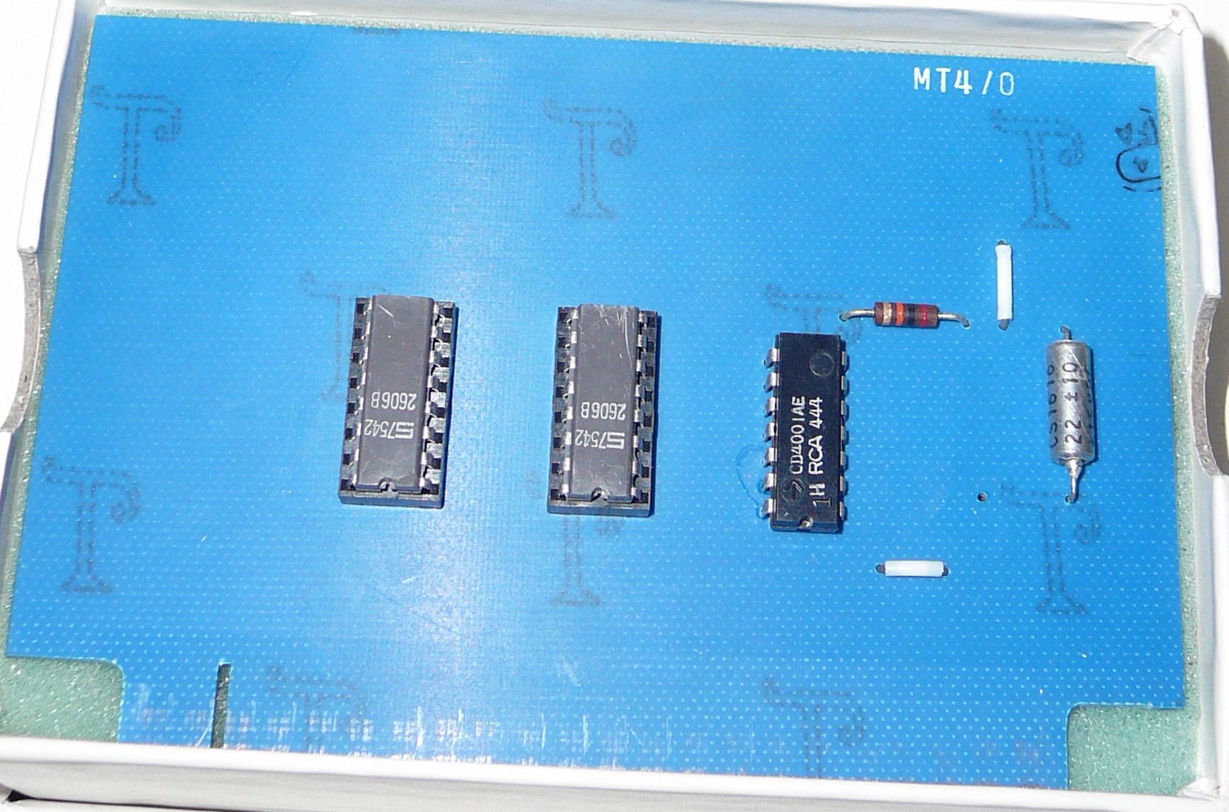
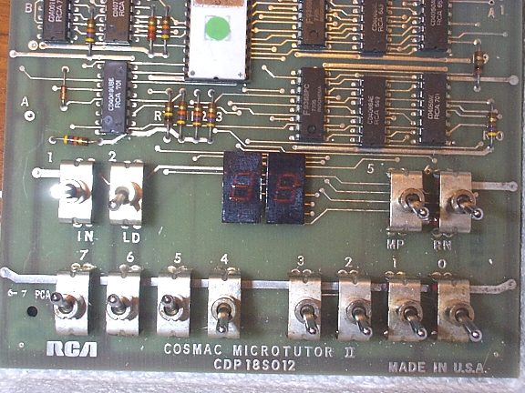
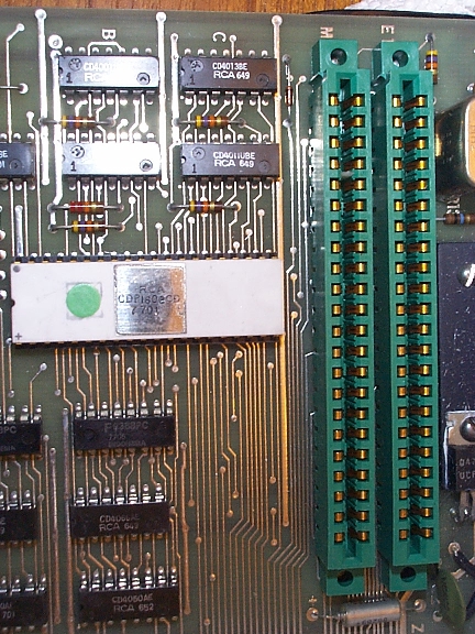
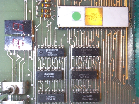

 RCA COSMAC Microtutor II

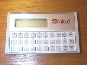 The 1802 also shows up in some unexpected places, like this
battery-powered hand-held unit.
The 1802 also shows up in some unexpected places, like this
battery-powered hand-held unit.
![[Large]](cdp1802-1.gif)
![[Large]](cdp1802-2.gif)
![[Large]](superelf-13.jpg)
![[Large]](superelf-12.jpg)
![[Large]](superelf-10.jpg)
![[Large]](superelf-9.jpg)
![[Medium]](cosmac-ad-mayjun78m.gif)
![[Large]](cosmac-ad-mayjun78.gif)