Once an equalizer is incorporated into a music system, the question quickly arises as to how best to use it. The most obvious way is as a "super tone control" unit, where control is extended from the familiar two or three controls to to ten control (or even 30 if 1/3 equalizers are used). While this approach is most useful and the results are dramatic in their ability to "liven" up a room, there still remains, with many, the desire to have some controlled matter inwhich to equalize the listening area without resorting to the use of expensive (and complicated) spectrum or real-time analyzers.
The first step in generating a self-contained room equalizing instrument is to design a pink noise generator to be used as a controlled source of noise across the audio spectrum. With the advent of medium scale integration and MOS digital technology, it is quite easy to create a pink noise generator using only one IC and a few passive components.
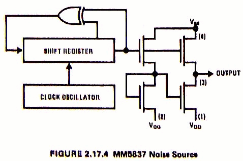
The MM5837 digital noise source is a MOS/MSI pseudo-random sequence generator, designed to produce a broadband white noise signal for audio applications. Unlike traditional semiconductor junction noise sources, the MM5837 provides very uniform noise quality and output amplitude. Originally designed for electronic organ and synthesizer applications, it can be directly applied to room equalization. Figure 2.17.4 shows a block diagram of the internal circuitry of the MM5837.
The output of the MM5837 is broadband white noise. In order to generate pink noise it is necessary to understand the difference between the two. White noise is characterized by a +3dB rise in amplitude per octave of frequency change (equal energy per constant bandwidth). Pink noise has flat amplitude response per octave change of frequency (equal energy per octave). Pink noise allows correlation between successive octave equalizer stages by insuring the same voltage amplitude is used each time as a reference standard.
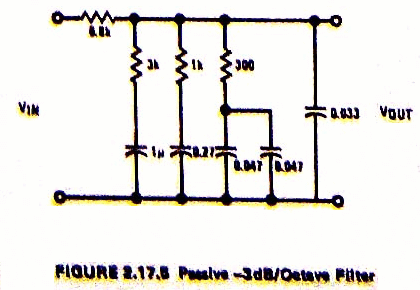
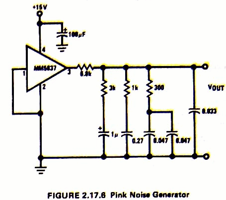
What is required to produce pink noise from a white noise source is simply a -3dB/octave filter. If capactive reactance varies at a rate of -6dB/octave then how can a slope of less than -6dB/octave be achieved? The answer is by cascading several stages of lag compensation such that the zeros of one stage partially cancel the poles of the next stage, etc. Such a network is shown as Figure 2.17.5 and exhibits a -3dB/octave characteristic (+/- 1/4dB) from 10 Hz to 40 kHz. The complete pink noise generator is given by Figure 2.17.6 and gives a flat spectral distribution over the audio band of 20 Hz to 20 kHz. The output at pin 3 is a 11.5 Vp-p random pulse train which is attenuated by the filter. Actual output is about 1 Vp-p AC pink noise riding on a 8.5 V DC level.