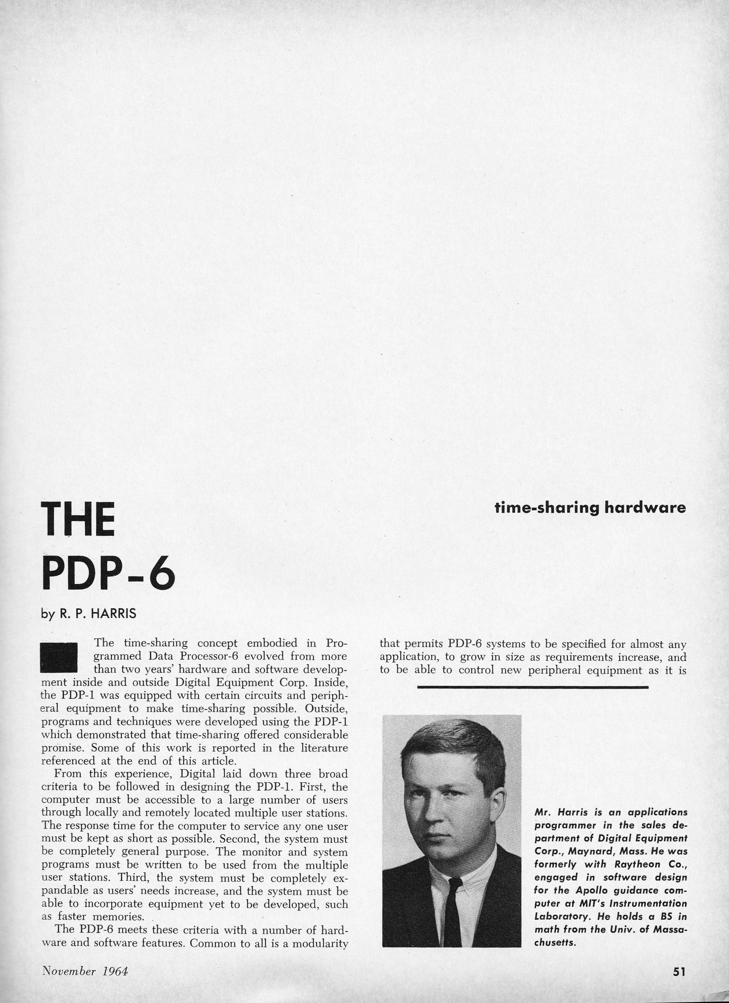
by R. P. Harris
The time-sharing concept embodied in Programmed Data Processor-6 evolved from more than two years' hardware and software development inside and outside Digital Equipment Corp. Inside, the PDP-1 was equipped with certain circuits and peripheral equipment to make time-sharing possible. Outside, programs and techniques were developed using the PDP-1 which demonstrated that time-sharing offered considerable promise. Some of this work is reported in the literature referenced at the end of the article.
From this experience, Digital laid down three broad criteria to be followed in designing the PDP-1. First, the computer must be accessible to a large number of users through locally and remotely located multiple user stations. The response time for the computer to service any one user must be kept as short as possible. Second, the system must be completely general purpose. THe monitor and system programs must be written to be used from the multiple user stations. Third, the system must be completely expandable as users' needs increase, and the system must be able to incorporate equipment yet to be developed, such as faster memories.
The PDP-6 meets these criteria with a number of hardware and software features. Common to all is a modularity that permits PDP-6 systems to be specified for almost any application, to grow in size as requirements increase, and to be able to control new peripheral equipment as it is developed and made available. Multiple processor capability is designed into the system. Asynchronous operation of processors, memories, and I/O equipment is the prime reason for this modularity.
Basic specifications of PDP-6 hardware are: 36-bit word length, core memories up to 262,144 words directly addressable, 363 instructions, and up to 128 input-output devices. The arithmetic processor has 16 accumulators, 15 of which double as index registers.
 From the point of view of the user at an input-output typewriter station,
it is primarily the monitor that makes the time-sharing system effective.
Because the monitor handles all scheduling and data manipulation problems,
several users can be on-line with the computer, editing, debugging, and
controlling I/O conversions. They can assemble, compile, and execute
programs under direct control. Traditional batch processing can be run
concurrently with these user activities, where the batch is treated as a
non-reactive user.
From the point of view of the user at an input-output typewriter station,
it is primarily the monitor that makes the time-sharing system effective.
Because the monitor handles all scheduling and data manipulation problems,
several users can be on-line with the computer, editing, debugging, and
controlling I/O conversions. They can assemble, compile, and execute
programs under direct control. Traditional batch processing can be run
concurrently with these user activities, where the batch is treated as a
non-reactive user.
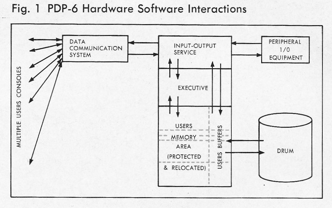
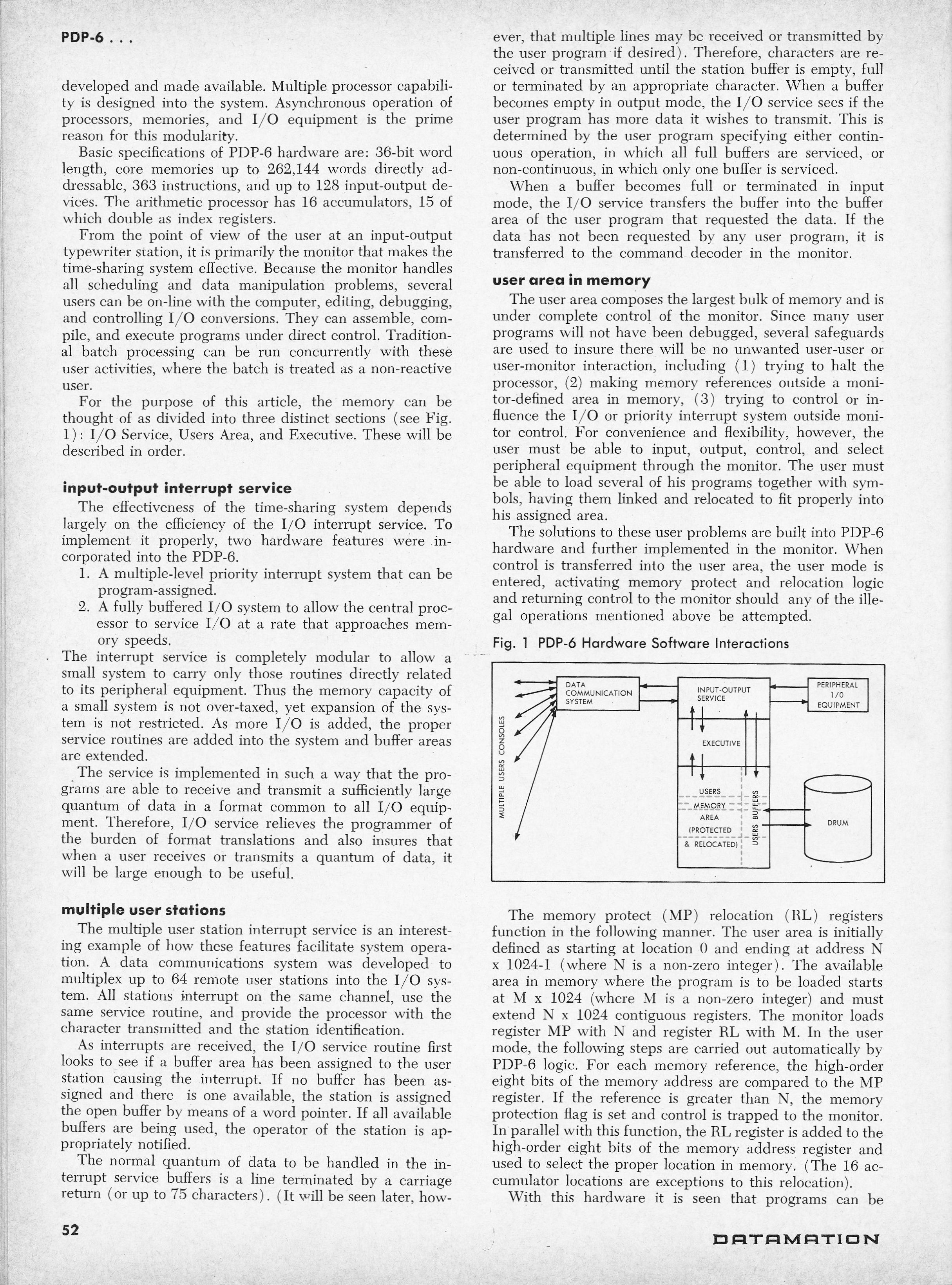
For the purpose of this article, the memory can be thought of as divided into three distinct sections (see Fig. 1): I/O Service, Users Area, and Executive. These will be described in order.
input-output interrupt service
The effectiveness of the time-sharing system depends largely on the
efficiency of the I/O interrupt service. To implement it properly, two
hardware features were incorporated into the PDP-6.
- A multiple-level priority interrupt system that can be program-assigned.
- A fully buffered I/O system to allow the central processor to service I/O at a rate that approaches memory speed.
The interrupt service is completely modular to allow a small system to carry only those routines directly related to its peripheral equipment. Thus the memory capacity of a small system is not over-taxed, yet expansion of the system is not restricted. As more I/O is added, the proper service routines are added inyo the system and buffer areas are extended.
The service is implemented in such a way that the programs are able to receive and transmit a sufficiently large quantum of data in a format common to all I/O equipment. Therefore, I/O service relieves the programmer of the burden of format translations and also insures that when a user receives or transmits a quantum of data, it will be large enough to be useful.
multiple user stations
The multiple user station interrupt service is an interesting example
of how these features facilitate system operation. A data communications
system was developed to multiplex up to 64 remote user stations into the
I/O system. All stations interrupt on the same channel, use the same
service routine, and provide the processor with the character transmitted
and te station identification.
As interrupts are received, the I/O service routine first looks to see if a buffer area has been assigned to the user station causing the interrupt. If no buffer has been assigned and there is one available, the station is assigned the open buffer by means of a word pointer. If all available buffers are being used, the operator of the station is appropriately notified.
The normal quantum of data to be handled in the interrupt service buffers is a line terminated by a carriage return (or up to 75 characters). (It will be seen later, however, that multiple lines may be received or transmitted by the user program if desired). Therefore, characters are received or transmitted until the station buffer is empty, full or terminated by an appropriate character. When a buffer becomes empty in output mode, the I/O service sees if the user program has more data it wishes to transmit. This is determined by the user program specifying either continuous operation, in which all full buffers are serviced, or non-continuous, in which only one buffer is serviced.
When a buffer becomes full or terminated in input mode, the I/O service transfers the buffer into the buffer area of the user program that requested the data. If the data has not been requested by any user program, it is transferred to the command decoder in the monitor.
user area in memory
The user area composes the largest bulk of memory and is under complete
control of the monitor. Since many user programs will not have been
debugged, several safeguards are used to insure there will be no unwanted
user-user or user-monitor interaction, including (1) trying to halt the
processor, (2) making memory references outside a monitor-defined area in
memory, (3) trying to control or influence the I/O or priority interrupt
system outside monitor control. For convenience and flexibility, however,
the user must be able to input, output, control, and select peripheral
equipment through the monitor. The user must be able to load several of his
programs together with symbols, having them linked and relocated to fit
properly into his assigned area.
The solutions to these user problems are built into PDP-6 hardware and further implemented in the monitor. When control is transferred to the user area, the user mode is entered, activating memory protect and relocation logic and returning control to the monitor should any of the illegal operations mentioned above be attempted.
The memory protect (MP) [and] relocation (RL) registers function in the following manner. The user area is initially defined as starting at location 0 and ending at address N × 1024-1 (where N is a non-zero integer). The available area in memory where the program is to be loaded starts at M × 1024 (where M is a non-zero integer) and must extend N × 1024 contiguous registers. The monitor loads register MP with N and register RL with M. In the user mode, the following steps are carried out automatically by PDP-6 logic. For each memory reference, the high-order eight bits of the memory address are compared to the MP register. If the reference is greater than N, the memory protection flag is set and control is trapped to the monitor. In parallel with this function, the RL register is added to the high-order eight bits of the mrmory address register and used to select the proper location in memory. (The 16 accumulator locations are exceptions to this relocation).
With this hardware it is seen that programs can be loaded into any available area in memory can can be from one to 255 blocks of 1024 words. While they are running it becomes impossible to reference any memory block lower than the one specified in RL; and any attempt to reference any memory block higher than the one specified in MP will be trapped and control transferred to the appropriate error sequence in the monitor.
Other circuits trap attempts to (1) execute a HALT, (2) leave the user mode, (3) influence the interrupt system, and (4) execute an instruction that interacts with the I/O system. All of these conditions trap to the monitor and are dispatched to the proper error routine and an appropriate diagnostic printed at the user console.
input-output control
There are 64 operation codes in the PDP-6 that are not decoded as instructions.
These programmed operators trap to the monitor for dispatching. Thirty-two
of these are left to the programmer to define additional software-implemented
instructions. The other 32 become the user-monitor link for I/O control.
At load time, the user declares to the monitor the number of 1024-word blocks of storage required for his program. This must include sufficient memory to buffer his I/O data. He then uses programmed operators to initiate I/O transfers to and from his buffer area.
Four commonly used programmed operators are:
- INITIALIZE - This performs several functions. The user includes with the command a device name, a device channel, a buffer area, and a set of condition bits. If the device is not available, control returns to the location following the call. If available, a set of ring buffers is set up in the area defined by the user. The device is assigned to the user and is initialized according to the conditions specified by the user. Control is then returned to the requesting program.
- INPUT - Input is commenced from the specified device into the current buffer of the user's buffer area. If a "wait" request is made, control will not return to the user program until at least one buffer has been filled; otherwise control is returned immediately. If the user specifies "continuous operator," all contiguous empty buffers will be filled before input is terminated. If the input is not to be "continuous," only one buffer will be filled and input will terminate.
- OUTPUT - Output is commenced on the specified device from the current buffer of the user's buffer area. The "wait" and "continuous;" conditions also apply with this command.
- RETURN - Returrn the specified device to the system. The user may therefore control the I/O portion of his program, specify the amounts of data to be received or sent with one command, and may stay on queue to do further processing, or release time to another user while waiting for input or output.
executive
The executive is a collection of programs remaining permanently in memory to
provide overall coordination and control of the total operating system. It
must allocate facilities, handle all command addressed to the system from the
user console, and coordinate I/O between the user and the I/O service. Its
principal function is to schedule all jobs to be processed from the run queue.
Once a user program has been given control, it can be removed from run status
by any of the following means:
- The program is completed and does not require further processing.
- The program has run for its allotted amount of time and must be re-scheduled.
- The program has issued an I/O command and issues a "wait" request.
- A program of higher priority must be run.
As a program is removed from run status, the executive must transfer control to another program as quickly as possible. In large memory, several programs can be waiting on the run queue and available immediately. If there is a large number of active users, a high speed drum provides secondary storage. Exchanges between drum and memory are made in parallel with processing. A direct access data control permits drum-to-memory transfers concurrent with the arithmetic processing.
The scheduling algorithm, to a large extent, determines the response time any one user will encounter when interacting with the machine at a user console. The most crucial parameter here is possibly the incremental run time - that is, the selected length of time during which program is allowed to run before being removed from run status. Obviously, as the time between switching from program to program becomes shorter, the time for the computer to service any one user decreases. However, the overhead time consumed by the monitor increases as a result. In the PDP-6, incremental run time is set at 100 ms, which is roughly equivalent to the maximum operating cycle of the user keyboards. With this type of response, the user would hardly ever perceive the difference between having the processor to himself and sharing it with several other users. This increment is variable, to be set for maximum system efficiency depending on system configuration, use, number of stations, etc.
At present, programs are scheduled in round robin fashion with programs returning from "I/O wait" requests given highest priority. In future systems, the scheduling algorithm will take into account such variables as: the length of time the program has run before being completed or I/O bound; the time elapsed since it was last on run queue; and the priority associated with each program. With parameters such as these, the scheduling program will decide in what order to put ptograms on run status.
The first PDP-6 time-sharing system is operational now at Digital Equipment Corp. in Maynard, Mass. It consists of an arithmetic processor, 16,384 words of core memory, a magnetic tape system, line printer, card reader, perforated tape reader and punch, and a data communications system with four multiple user consoles. Using this system, larger and more sophisticated time-sharing systems are being developed in a time-shared environment.
The first PDP-6 time-sharing system produced for sale is scheduled for installation at the University of Western Australia in January, 1965.
Original scans:
 |
 |
 |