Milt Schwartz
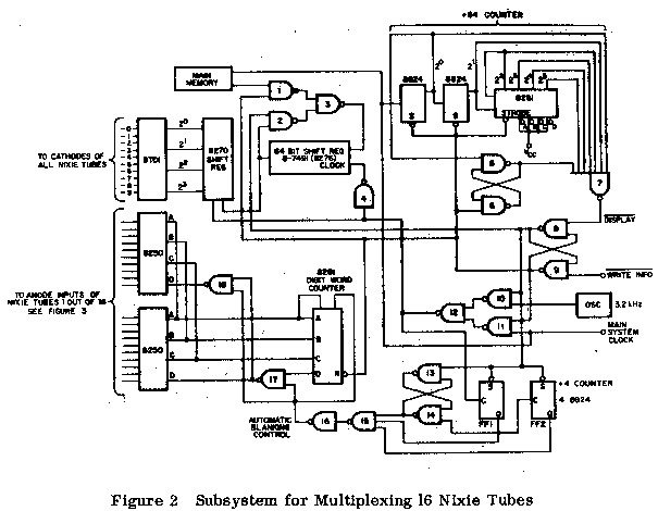
With the advent of the new Burroughs Nixie Tube designed for multiplexing techniques, a new approach to readouts can be taken which will result in substantial can count savings. Specifically only one decoder/driver will be necessary to drive up to 20 Nixie Tubes, though a memory element will be necessary to store the BCD codes, i.e., for 20 tubes one needs 20 four-bit words (assuming that the digits 0 through 9 are to be displayed). This technique can be achieved by combining the 8270 (four-bit shift), 8T01 (Nixie® decoder/driver) and 8281 (four-bit binary counter), 7491 (8-bit shift register), in a small subsystem (see Figure 2).
- All Discrete Devices
- Advantage - large selection of components
- Disadvantage - complexity of interconnects and large number of devices
- Gates and Flip-Flops
- Advantages - fewer components - many types offered
- Disadvantages - high can count and complex interconnect
- Complex Arrays
- Advantages - fewest components and interconnects should be most economical
- Disadvantages - small selection of the market; therefore, possible single sourcing
Concluding, then, the best approach from an economical and least number of components viewpoint, which are essential to the desk top calculator or instrumentation market, is the third approach listed above.
Functional Description
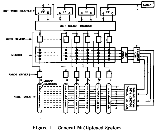
Figure 1 is a block diagram of a logic subsystem for multiplexing that recently appeared in an application note by Burroughs Corporation. [1] (See Figure 2 for detailed drawing.) The system has a sequentially

addressable word select memory with a capacity of N words where N is also the number of Nixie indicators in the system. Each word consists of at least four bits which represent, in binary form, the number of the corresponding decimal digit. The recirculation loop and the write circuits for the memory are not show in Figure 1, but they would normally be required.
When displaying an N digit number, as illustrated in Figure 1, the N words of the memory are sequentially read out at a constant rate that is determined by the system Clock. Each time a word is read out, it is rewritten in the same position of the Memory, thus the information is preserved. When the displayed information is to be altered in one or more of the digit positions, the new information is written into the corresponding word position in the memory, just after the existing words are read. [1]

Referring to Figures 1 and 2, eight packages of 7491 (8-bit shift register) or 16 packages of 8270 (4-bit shift register) are used to hold the 16 four-bit BCD coded words that determine what each Nixie tube will display. A four-bit binary counter (8281) is used as the digit word counter. A divide by four counter (2-8822) is used to enable the data after every 4th clock pulse. Two one-out-of-eight decoders (8250) are used to implement the digit select decoder, which drives the appropriate anode through a circuit such as shown in Figure 1. The Nixie driver (8T01) [2] accepts the four-bit BCD code from memory and drives the cathodes of the tubes. The Nixie driver must have a minimum collector breakdown on 100V and be able to sink 15 mA. The Signetics dielectrically isolated 8T01 has these capabilities. Other advantages of dielectric isolation are the following:
- Evenly distributed voltage gradients (less chance of leakage due to high potentials across small junctions).
- Absence of inadvertent MOS action (surface inversion causing leakage paths).
- Radiation resistance (many pieces of equipment, i.e., CRO, etc., emit "soft" X-rays).
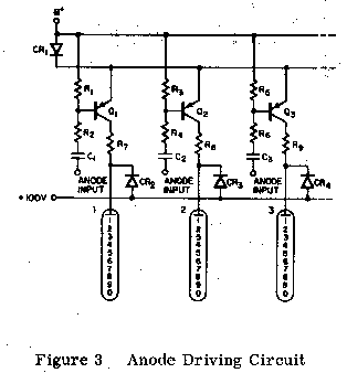
Figure 3 shows a constant voltage anode driver circuit. In the circuit, one of the transistors, Q1, Q2, Q3, etc., is turned on while the other are held off. Diode CR1, in conjunction with the base resistors R1, R3, R5, serve to back-bias the off transistors. To turn transistor Q1 on, a negative pulse is applied to input number one. The components R2 and C1 are chosen to maintain transistor Q1 in the on condition for the full period required by the system timing.
C1 = 1 µF 250V
Q1 = 2N4036
The collectors of the constant current drivers are connected through catching diodes CR2, CR3, and CR4 to a +100 volt buss. This is done to prevent excessive voltages from appearing across these transistors. Without these diodes, overshoots would tend to occur due ot the characteristics of the Nixie tube.
The 3.2 kHz oscillator results in a 50 Hz signal to an individual anode input. This is sufficiently greater than minimum eye "flicker" frequency (approximately 24 Hz). The upper limit of this oscillator could be 10 kHz which will result in a minimum "ON" time of 100 microseconds for each tube. [2] If the main clock repetition rate falls between these limits, there is no need for the oscillator.
Detailed Description
Refer to Figure 2 and Figure 3. The 64-bit shift right register is loaded from the main memory with the coded numbers to be displayed by each tube. The operation is as follows:
The write information input (Figure 1) normally logic "1" is set to a logic "0" level (pulsed operation). This allows the words in main memory to be shifted into the register. Also, the main clock from the calculator advances a counter such that after 64 counts the display input is set to logic "0" (pulsed operation), inhibiting any further counter advancement, or loading of the shift register. Simultaneously, as the display input goes to a logic "0", the 3.2 kHz oscillator starts cycling the 64-bit shift register. Simultaneously, as the display input goes to a logic "0", the 3.2 kHz oscillator starts cycling the 64-bit shift register.
The above is accomplished via the following individual steps.
The latch formed by gates 8 and 9 is initially set such that the output of 8 is a logic "0" level. The output of 8 inhibits the divide by four counter, the 8281 (Digit Word Counter), and conditions the latch formed by gates 13 and 14 such that the output of 14 is set to a logic "0" level. As a result of this action, the output of 16 is a logic "0" level with forces the output of gates 17 and 18 to logic "1" levels.
Logic "1" levels at the "D" input of an 8250 (one out of eight decoder) inhibits the output by forcing them all to logic "1" levels.
At the point in time just prior to the negative-going-edge of the 64th clock pluse, all anode inputs to the NIXIE tubes have been at logic "1" levels. (Logic "1" from the 8250's.)
After the 64th pulse (from the main system clock), the divide by 64 counter is decoded and the output of gate 7 goes to logic "0", forcing the latch formed by gates 8 and 9 such that the output of 8 is set to a logic "1" level, thereby releasing the inhibit on the divide by four and 8281 counters.
Also, all the codes for the digits to be displayed are in the 64 bit shift register and the systemis now ready for multiplexing to commence.
Now the system is in the multiplex routine, which is as follows:
The system is clocked by the 3.2 kHz oscillator.The divide by four counter controls the anode strobing by holding the outputs of the 8250's at logic "1" levels for 4 clock pulses, then allowing one output to make the "1" to "0" transition thus firing the number on NIXIE tube viz. the input capacitor (1 µf).
The TC time constant (1K, 1 µf) allows the tube to conduct for approximately 300 microseconds.
The next clock pulse (5th pulse) shuts off the 8251's. When the negative-going-edge of the 8th (eighth) pulse has occurred, then the number 2 NIXIE will be fired. The process repeats for all 16 tubes.
The 8281 (Digit Word Counter) is advanced by the divide by four counter. Therefore, the 8281 gets advanced after the negative-going-edge of every 4th pulse issued by the oscillator.
The outputs of the 8281 are decoded by the 8250's which fire the anodes of the NIXIE tubes.
The 64-bit shift register circulates the 16 BCD coded words that are to be displayed.
The 8270 (4-bit shift register) receives the BCD information from the 64-bit shift register and in turn is decoded by the 8T01 (BCD to Decimal) which drives the cathodes of all 16 tubes simultaneously.
Thus the operation is complete. The automatic blanking control ensures that the tubes are not conducting for 4 shift pulses while the next BCD coded word is shifted into the 8270.
NOTES
-
Reprinted from Burroughs Application Note "Multiplexed Operation
of NIXIE Tubes," by A. Somlyody; Manager, Applications Engineering.
- "The conclusion is that for high-current pulsed operation, the NIXIE indicator requires a higher prebias voltage to minimum "off" cathode glow. For a peak anode current of IA < 15mA, the cathode driver transistors should have a minimum collector breakdown voltage of 100 volts. Integrated circuit drivers that have lower than 100 volts breakdown voltage, therefore, are not suitable for use in timesharing systems." Refer to Burroughs Application Node "Multiplexed Operation of NIXIE Tubes," Page 5, by A. Somlyody.
