The board I have came with a three-page photocopy containing
the following text.
The Keyboard Executive software is contained in a single
1702A type EPROM in the location allocated for IC15 on the MMD-1
microcomputer. A program listing is provided in the following
pages. Then, in describing how KEX operates, we shall quote
from the article in the June, 1976 issue of
Radio-Electronics magazine by Jonathan A. Titus.
Keyboard Executive Program
                       *000 000
000 000 303            JMP
000 001 070            START
000 002 000            0
                       /JUMP UP TO R/W MEMORY TO BE USED BY RESTARTS & VECTORED INTERRUPTS
                       *000 010
000 010 303            JMP
000 011 010            010
000 012 003            003
                       *000 020
000 020 303            JMP
000 021 020            020
000 022 003            003
                       *000 030
000 030 303            JMP
000 031 030            030
000 032 003            003
                       *000 040
000 040 303            JMP
000 041 040            040
000 042 003            003
                       *000 050
000 050 303            JMP
000 051 050            050
000 052 003            003
                       *000 060
000 050 303            JMP
000 061 060            060
000 062 003            003
                       /BEGINNING OF MAIN PROGRAM
                       *000 070
000 070 061  START,    LXISP    /SET STACK POINTER TO TOP OF R/W MEM.
000 071 000            000
000 072 004            004
000 073 041            LXIH     /INITIAL VALUE FOR H & L
000 074 000            000
000 075 003            003
000 076 116  POINTA,   MOVCM    /LOAD MEM DATA INTO TEMP DATA BUFFER
000 077 174            MOVAH    /OUTPUT HI TO LED'S
000 100 323            OUT
000 101 001            001
000 102 175            MOVAL    /OUTPUT LOW TO LED'S
000 103 323            OUT
000 104 000            000
000 105 171  POINTB,   MOVAC    /OUTPUT TEMP. DATA BUFFER DATA TO LED'S
000 106 323            OUT
000 107 002            002
000 110 315  POINTC,   CALL     /WAIT AND INPUT NEXT KEY CLOSURE
000 111 315            KBRD
000 112 000            0
000 113 376            CPI
000 114 010            010
000 115 322            JNC      /JUMP IF KEY WAS < 010
000 116 134            POINT D  /(0-7, OCTAL DIGIT)
000 117 000            0
000 120 107            MOVBA    /SAVE KEY CODE
000 121 171            MOVAC    /GET OLD VALUE
000 122 027            RAL      /ROTATE 3 TIMES
000 123 027            RAL
000 124 027            RAL
000 125 346            ANI      /MASK OUT LEAST SIG. OCTAL DIGIT
000 126 370            370
000 127 260            ORAB     /OR IN NEW OCTAL DIGIT
000 130 117            MOVCA    /PUT NEW DATA BACK INTO BUFFER
000 131 303            JMP
000 132 105            POINT B
000 133 000            0
000 134 376  POINTD,   CPI
000 135 011            011      /"L" KEY
000 136 302            JNZ      /JUMP IF NOT AN "L"
000 137 145            POINT E
000 140 000            0
000 141 151            MOVLC    /PUT BUFFER DATA IN L
000 142 303            JMP
000 143 076            POINT A
000 144 000            0
000 145 376  POINTE,   CPI
000 146 010            010      /"H" KEY
000 147 302            JNZ      /JUMP IF NOT AN "H"
000 150 156            POINT F
000 151 000            0
000 152 141            MOVHC    /PUT BUFFER DATA IN H
000 153 303            JMP
000 154 076            POINT A
000 155 000            0
000 156 376  POINTF,   CPI
000 157 013            013      /"S" KEY
000 160 302            JNZ      /JUMP IF NOT "S"
000 161 170            POINT G
000 162 000            0
000 163 161            MOVMC    /PUT TEMP. DATA INTO MEMORY
000 164 043            INHX     /INCREMENT H & L
000 165 303            JMP
000 166 076            POINT A
000 167 000            0
000 170 376  POINTG,   CPI
000 171 012            012      /"G" KEY
000 172 302            JNZ
000 173 110            POINT C
000 174 000            0
000 175 351            PCHL     /GO EXECUTE PGM POINTED TO BY H & L
                       /THIS 10 MSEC DELAY DISTRUBS NO REGISTERS OR FLAG
                       *000 277
000 277 365  TIMOUT,   PUSHPSW  /SAVE REGISTERS
000 300 325            PUSHD
000 301 021            LXID     /LOAD D & E WITH VALUE TO BE DECREMENTED
000 302 046            046
000 303 001            001
000 304 033  MORE,     DCXD     /JUMP IN THIS LOOP UNTIL
000 305 172            MOVAD    /D & E ARE BOTH ZERO
000 306 263            ORAE
000 307 302            JNZ
000 310 304            MORE
000 311 000            0
000 312 321            POPD
000 313 361            POPPSW   /RESTORE REGISTERS
000 314 311            RET
                       /THE KBRD ROUTINE DEBOUNCES KEY CLOSURES
                       /AND TRANSLATES KEY CODES
                       /FLAGS AND REG A ARE CHANGED
                       /D0-D3 = CODE; D4-D7 = ZERO
000 315 333  KBRD,     IN       /INPUT FROM KEYBOARD ENCODERS
000 316 000            000
000 317 267            ORAA     /SET FLAGS
000 320 372            JM       /JMP BACK IF LAST KEY NOT RELEASED
000 321 315            KBRD
000 322 000            0
000 323 315            CALL     /WAIT 10 MSEC
000 324 277            TIMOUT
000 325 000            0
000 326 333  FLAGCK,   IN
000 327 000            000
000 330 267            ORAA
000 331 362            JP       /JUMP BACK TO WAIT FOR A NEW
000 332 362            FLAGCK   /KEY TO BE PRESSED
000 333 000            0
000 334 315            CALL     /WAIT 10 MSEC FOR BOUNCING
000 335 277            TIMOUT
000 336 000            0
000 337 333            IN
000 340 000            000
000 341 267            ORAA
000 342 362            JP       /JUMP BACK IF NEW KEY NOT STILL
000 343 326            FLAGCK   /PRESSED (FALSE ALARM)
000 344 000            0
000 345 346            ANI      /MASK OUT ALL BUT KEY CODE
000 346 017            017
000 347 345            PUSHH    /SAVE H & L
000 350 046            MVIH     /ZERO H REG
000 351 000            000
000 352 306            ADI      /ADD THE ADDRESS OF THE BEGINNING
000 353 360            360      /OF THE TABLE TO THE KEY CODE
000 354 157            MOVLA    /
000 355 176            MOVAM    /FETCH NEW VALUE FROM TABLE
000 356 341            POPH     /RESTORE H & L
000 357 311            RET
                       /THIS TRANSLATION TABLE CONVERTS THE CODE
                       /GENERATED BY KEY CLOSURES TO THE CODE
                       /USED BY THE MAIN KEX PROGRAM
000 360 000  TABLE,    000
000 361 001            001
000 362 002            002
000 363 003            003
000 364 004            004
000 365 005            005
000 366 006            006
000 367 007            007
000 370 013            013      /S
000 371 000            000      /THIS CODE CAN'T BE GENERATED
000 372 017            017      /C
000 373 012            012      /G
000 374 010            010      /H
000 375 011            011      /L
000 376 015            015      /A
000 377 016            016      /B
How KEX Operates
The Keyboard Executive software is contained in a single 1702A-type
PROM in the location allocated for IC15. This contains all the necessary
software to operate the keyboard and the LED displays. This is our
software-controlled "front panel," since the keys and LEDs perform
functions determined by the KEX software.
Whenever the R key is depressed, the 8080A CPU will start to execute
the program that starts at location 0. Looking at the software listing
for the KEX program, you will see that immediately after starting at
location 0, the software instructions cause the computer to jump to
location HI=000, LO=070 (HI=000 throughout the KEX program), where we
start the program by pointing to the first R/W memory address (003 000).
The address and the data in that location are displayed on the three
output ports. This is done between POINTA and POINTC
in the program.
The software between POINTC and POINTD will do the
necessary tasks to
input new data from the keyboard and shift the data onto the LEDs.
The shifting is done inside the 8080A with software instructions. Doing
this by hardware would require many more ICs, but it takes relatively
few software steps.
The software instructions at POINTD, POINTE,
POINTF, and POINTG make up
what is called a command decoder. The software decodes the key switches
into real actions. Depressing H or L causes the data
temporarily stored
in the 8080A as numeric key inputs to be output to either the HI or LO
set of LEDs. The S key causes the current or new data to be put back
into the current memory location. Depressing G causes the computer to
use the HI and LO address as the starting point for a new program.
The TIMOUT and KBRD software subroutines have specific tasks. The
TIMOUT subroutine will count its way through various loops for about
10 milliseconds, while the KBRD subroutine will input a code from the
keyboard. The KBRD subroutine has some unique features that illustrate
an interesting hardware-software tradeoff. The key switches used in
the MMD-1 are not bounce free, so that when the switches are opened or
closed, they can often remake or rebrake the contacts. This can be confusing
to the computer since it can't distinguish between a real switch closure and
a bounce. We don't want the computer to sense each each bounce as a key
closure so we would like some way to filter them out. Additional circuitry
including latches, clocks and monostables could do this for us, but it
complicates the system. We can also do the debouncing via software.
The KBRD subroutine will recognize any key closure, but it will only input
the key codes after being sure that the key is closed and not bouncing.
It does this by waiting after sensing a closure and then rechecking the
switch to be sure it is still closed. It also checks when we release a key
to be sure that it has stopped bouncing before it tries to sense another
key being depressed by the user. We have traded some additional software
steps for a great deal of hardware. Since there was plenty of PROM left,
it was easy to include.
The TIMOUT and KBRD software segments have been set up as subroutines and
can be used in your software and in the experiments. Each of these subroutines
may be started with a CALL instruction, 315.
The TIMOUT subroutine does not
affect any of the registers or flags and it only serves to delay the
software flow by 10 ms.
An important distinction between the 8008 and the 8080 processors is in the
use of subroutines. In the 8008, return-pointer addresses were stored in
the 8008 IC itself. In the 8080, these return-pointer addresses are stored
in a portion of the R/W memory. This is called a "stack" area. Whenever
a subroutine is used, we want to execute the subroutine and then return back
to the normal program flow. These return addresses are very important to
the computer since they provide the only link between the subroutine and the
main program. If we are to store them in a portion of R/W memory, the computer
must know where this storage area is, if it is to be able to use the addresses
properly. In the KEX software, this is preset to be the top of the R/W
memory with instructions at locations 070, 071 and 072. The LXISP
instruction
loads an internal 8080 stack-pointer register to HI=004, LO=000. Since the
stack-pointer register is decremented to point to a new location before
anything is stored, the first stack location will be HI=003, LO=377. Check
your 16-bit binary numbers if this looks a little confusing.
You can use the stack as set up by the KEX (generally a good idea) or you
can put your own stack anywhere you want, just by using the LXISP
instruction.
Remember to avoid the stack area when writing your programs. Remember, too,
that you can't put the stack in an area of nonexistent memory or in PROM.
| 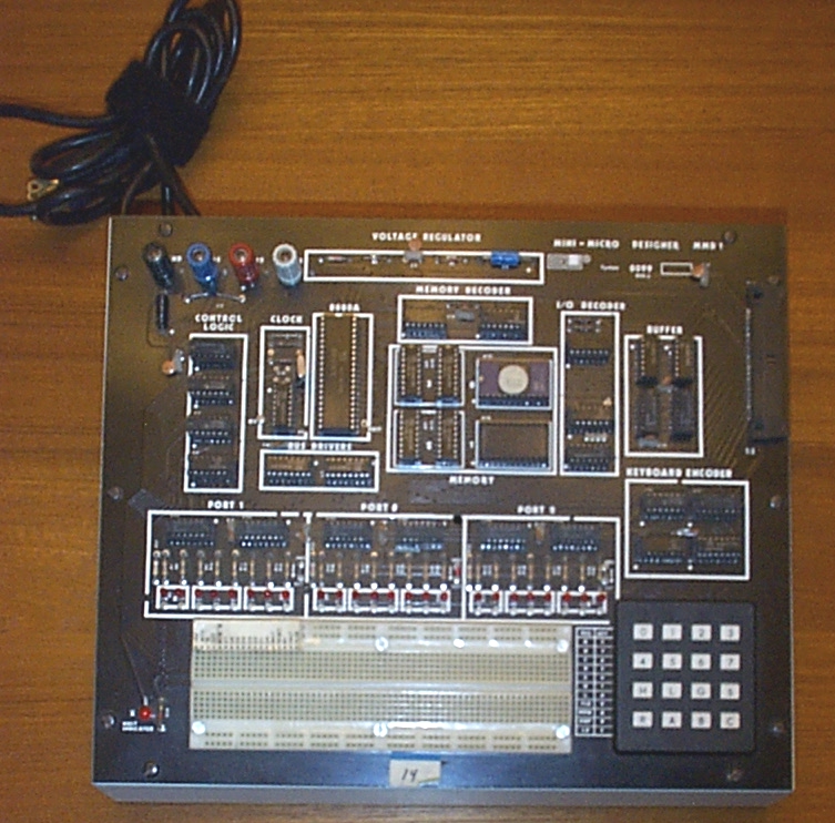
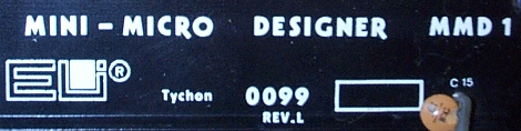 The MMD-1 is a development system for the 8080A microprocessor
from circa 1977.
The MMD-1 is a development system for the 8080A microprocessor
from circa 1977.
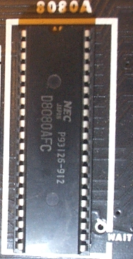 This particular board has an NEC-fabbed 8080A, a second
source manufacturer.
The 8080 was originally introduced by Intel in 1974 as
a more powerful NMOS version of the 8008. The 8080
requires +12, +5 and -5 volt power supplies as well
as two clocks to operate.
This particular board has an NEC-fabbed 8080A, a second
source manufacturer.
The 8080 was originally introduced by Intel in 1974 as
a more powerful NMOS version of the 8008. The 8080
requires +12, +5 and -5 volt power supplies as well
as two clocks to operate.
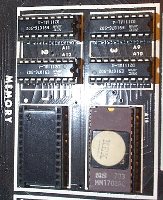 The board has a monitor program of sorts, stored in a 1702A EPROM.
Details about this monitor are below.
The board has a monitor program of sorts, stored in a 1702A EPROM.
Details about this monitor are below.