After a phone call to Jameco, I received four pages of faxed instructions for this device.
|
|
|
|
|
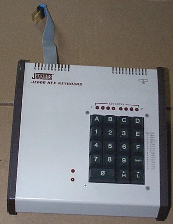
I have two of these keyboards that came from a surplus
equipment supplier. These were originally built from kits,
apparently for a vocational school. Based on the age
of the parts and the instructions, it appears Jameco sold
these in the early 1980's.
After a phone call to Jameco, I received four pages of faxed instructions for this device.
|
|
|
|
I received four pages of documentation from Jameco via fax.
These pages have a copyright date of 1979.
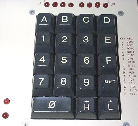
FEATURES:
KEYBOARD OPERATION: USER KEYS: "SHIFT," "H" and "L" Each key has a de-bounce circuit that provides a logic high output when pressed and is capable of driving one TTL load. In addition, the "SHIFT" key is connected to a bi-stable circuit to provide a toggle-switch action for controlling remote circuits. This bistable output is capable of driving approximately 4 TTL loads. The LED indicator (LED9) is on when logic "ONE" is at the output. HEXADECIMAL KEYS "0" to "9" and "A" to "F" Each key closure operates the encoder chip "U1" to produce a hexadecimal digit at its output. The logic is such that if two (2) keys are pressed at the same time, the signal at pin 24 of that IC (U1) will go to logic zero to clear U5, thus preventing false entries. See "Encoder Timing Diagram" for normal entries. Note that the data from the previous entry is transferred to the second quad latch (U2). If, for example, you enter the numbers "A6" the register will contain "10100110," the least significant bit being on the right. The latched outputs are capable of driving approximately four (4) TTL loads.
(Click here for very large version.)
|
|
|
|
The U1 integrated circuit in the schematic is a Harris HD-0165 Keyboard Encoder.
You can see a datasheet (Adobe Acrobat format) here. |
Click here for the home page.
Click here for the wanted page.
Updated January 8, 2010