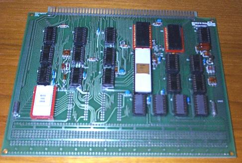
This board is part number 2650PC1500. Interestingly, all of the integrated circuits are socketed.

|
| |
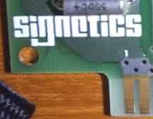
| The processor is, as you might expect, a Signetics. The chip number is 2650I. | This is a support chip, also in a ceramic package. |
Above the processor are a pair of Signetics N8T31N with date codes of 7617.
Beneath and to the right of the processor are four Signetics 2112B chips, each with a date code of 7640.
Update:
I received the following e-mail:
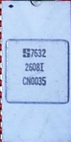
I might be able to help you with the 2650 card. The 2608 is the Signetics 2650 Pipbug 1K Monitor Debug ROM. The CPU is the 1 MHz 2650.Pipbug uses ROM locations 0000-03FF and RAM starts at 0400.
It uses software to run simple 110 bps TTY. The send and receive are connected to the flag and sense pins of the CPU.
Update:
I picked up a set of old documents and in it was a brochure from Signetics that identifies the board as a Signetics Adaptable Board Computer.From the brochure:
The Adaptable Board Computer microprocessor development hardware system provides the necessary hardware to develop a system that approximates, as closely as possible, your final system configuration.By using the ABC hardware, design and assembly time can be reduced significantly.
The Adaptable Board Computers versatility and flexibility is accomplished by including space on the board for additional components and also by a system of jumper wires which can be used to change the basic board configuration.
The ABC system is supplied complete with the 2650 microprocessor, 1K bytes of ROM with PIPBUG, (a loader, editor, and debug program), 512 bytes of RAM, I/O ports (serial and parallel), and a system clock. For those applications where additional components are required to more closely approximate the final system, the ABC board contains additional unused plated through holes to accomodate those components.
Connections to the existing components can then be made via jumper wires or wire-wrap connections. Thus, the user cannot only add components to expand memory, add I/O or implement additional control features in his current application, but he can also reconfigure the system to satisfy future requirements. The ABC system can be purchased assembled or unassembled.
Features
- Expandable printed circuit card:
Unused area on card filled with plated through holes on .300 in. centers for wirewrap sockets- 1k bytes of PIPBUG* ROM (in socket) between units
- 512 bytes of RAM
- Two latched I/O ports
- Four non-extended I/O read/write user strobes
- Tri-state buffers on data, address and control lines
- Serial input/output port
- Single +5 volt supply requirement (1.7A max) for card and 20 mA current loop interface (+/- 12 volt supply for RS232 interface)
- Simple memory and I/O port decoding with two 16 pin dips
- Interrupt and single step capability
- Simple clock configured from dual monostable multivibrator
- 24k memory expansion capability
- Directly compatible with 4k RAM card (2650PC-2000) and power supply demonstration base (2650-DS2000)
- Card dimensions: 8 in. by 6.875 in. with a 100 pin connector along with 8 in. dimension
Options
- 1k bytes of PROM in place of ROM.
- 512 bytes of PROM or ROM in place of RAM.
- Asynchronous operation capability.
- External clock input.
- Interrupt vector from Port C.
Interface
- Terminal interface jumper selectable.
A. W4 to W5 and W6 to W7 jumpers select the 20mA current loop mode.
B. W3 to W4 and W7 to W8 jumpers select the RS232 mode.- Normally high input line (10k pull up resistor on each): INTREQ, PAUSE, RESET, WBAC, WBAD, CKC, CKD
- Plated through holes are available at each connector pin to allow for insertion of wirewrap pins.
- Edge connector supplied with each card.
- To allow for external clock input, remove jumper W9-W10.
- Asynchronous operation by removing jumper W1 to W2 and driving OPACK.
- During vectored interrupts, it is possible to allow Port C to place the interrupt address on the data bus by removing jumper W21-W22 and jumpering W22-W23.
Memory
Modifications to the basic configuration can be made to provide a mix of RAM/PROM/ROM memories. PROM memories can be used in place of the PIPBUG ROM by removing the ROM from its socket and adding one or two 82S115 PROM's (512x8). Area and plated through holes are provided on the card for insertion of sockets for the PROM's or the PROM's themselves. Decoding for the PROM's has been provided by ABC 1500 logic.
Data and address lines for 2112 RAM's and 82S129 PROM's or 82S229 ROM's are identical. It is, therefore, possible to use PROM's and/or ROM's in place of RAM. This option will require removal of the RAM's (two per block), and changing the jumper for each 256 byte block of PROM or ROM added.