GLOW LAMPS
Glow lamps are small neon lamps. These cold-cathode, gas-discharge devices operate by passing electric current through low pressure neon gas. This ionizes the gas and generates photons.

The characteristics of glow lamps make them useful for other purposes besides light.

If anyone has a good source for NE-97 neon glow lamps (4AC type), please send me an e-mail.

GLOW LAMP TYPES
NE-2AS     The NE-2AS is a modification of an indicator lamp, (NE-2A), with specific voltage specifications, tinned leads, an extinguishing voltage test, and a shorter length than the NE-2.
NE-2L     The NE-2L is a modification of an indicator lamp, (NE-2E), with tighter voltage tolerances, mild radioactive additive for the reduction of dark effect, and Dri-Film coating for high leakage resistance. This lamp has a formed tip which provides better end-on viewing than the random tipped lamps.
NE-2S     The NE-2S is a modification of the NE-2 indicator lamp with reduced bulb diameter, specified voltage ranges, tinned leads, an extinguishing voltage test, mild radioactive additive for the reduction of dark effect, and Dri-Film coating for high leakage resistance.
NE-2U     The NE-2U is a high brightness indicator lamp often used to excite photoconductors. The greater effectiveness of the radioactive additive used in this lamp make it a logical choice over its NE-2H brother for electronic usage. It is recommended for applications where stability of lamp voltage characteristics is not a design criteria. The formed tip provides an overall length which is shorter than many glow lamps, as well as better end-on viewing, where desired.
NE-2V     The NE-2V is a standard brightness indicator lamp sometimes used in circuit component applications. It incorporates a shorter overall length than most glow lamps, a formed tip for easier end-on viewing, and a mild radioactive additive for the reduction of dark effect. It is one of the lower price neons.
NE-3   8AA   A neon lamp utilizing a clear round-end bulb mounted in a telephone slide base. The round-end bulb provides undistorted end-on viewing. The telephone slide base is one solution to front-end replacement of panel mounted lighting units.
NE-4   8AB   The NE-4 is a combination of the random-tipped NE-2 lamp and the telephone slide base. It offers the same front-end accessibility as the NE-3 and is lower in price.
NE-5   8AC   The NE-5 lamp is the NE-96 with telephone slide base. It is designed for those applications where a replaceable lamp is a necessity. The wide differential between breakdown and maintaining voltage suggests this lamp for those applications where maximum output signal is desired. A mild radioactive additive is included in the lamp.
NE-16   7AA   The NE-16 is intended primarily for voltage regulation applications. It meets the requirements of MIL-E-1/283 for the JAN 991 regulator tube. A mild radioactive additive for the reduction of dark effect is included in the lamp.
NE-23   5AB   The NE-23 is a modification of the NE-2 indicator lamp with mild radioactive additive for the reduction of dark effect. Both its low cost and stable characteristics following aging account for it s popularity.
  5AB-A   The 5AB-A is a pre-aged 5AB. A breakdown and maintaining voltage test has been added along with an extinguishing voltage test. Dri-Film coating increases the leakage resistance. This is the least expensive pre-aged circuit component in the line.
  5AB-B   The 5AB-B is a selected version of the 5AB-A. Where closer voltage specifications are required this is one of the logical choices over the 5AB-A.
  5AB-C   The 5AB-C is also a selected version of the 5AB-A. Slightly higher breakdown and maintaining range will give advantages in some circuits.
NE-51S     The NE-51S is a modification of the NE-51 indicator lamp with specified voltage ranges and an extinguishing voltage test.
NE-67   6AC   The NE-67 is a modification of the NE-51 indicator lamp with Dri-Film coating incorporated within the base. This Dri-Film counteracts the leakage resistance problem inherent in many based lamps because of conduction across the basing cements.
NE-68   5AC   The NE-68 is designed primarily for voltage regulation purposes. This lamp, and its tighter tolerance brother the NE-68A, are recommended for those applications where a partially stabilized lamp is required. The lamp contains a mild radioactive additive.
NE-68A     This tighter tolerance brother of the NE-68 is also recommended for voltage regulation usage. The lamp contains a mild radioactive additive and a dark starting test rounds out the specifications on this partially stabilized lamp.
NE-75     The NE-75 is a modification of the NE-2E indicator lamp with an extinguishing voltage test.
NE-76   5AG-A   This neon lamp has the tightest breakdown voltage tolerance - ±4 volts - of all GE glow lamps. Maintaining voltage is also held within ±5 volts. The lamps are all preaged, polarity marked, and contain a mild radioactive additive for the reduction of dark effect. The tight voltage characteristics and pre-aging treatment ideally suit this lamp for use in multivibrators, relaxation oscillators and other close tolerance applications.
NE-77     The NE~77, externally, is physically the same as an NE~2 glow lamp, but has a third, trigger electrode. A low current signal applied between cathode and trigger will ionize the lamp permitting current to flow between anode and cathode. Current will continue to flow until the work circuit is interrupted.
NE-80     The NE-80 with a 50-58 volt maintaining voltage at 0.1 ma., is the closest tolerance, low current voltage regulator. It is preaged and contains a mild radioactive additive for the reduction of dark effect.
NE-81   5AG   The NE-81 is closely related to the NE-76, but has somewhat wider tolerance on breakdown voltage. It too, is preaged and contains a mild radioactive additive, has Dri-Film coating, and an extinguishing voltage test. This lamp is rated @ 0.1 and 0.3 ma.
NE-83   5AH   This "high-current" lamp shows promise wherever greater current carrying capacity is required. The lamp's differential between breakdown and maintairiing volts is somewhat greater than the NE-23 family, but not as large as is the case for the NE-96 and NE-97. It's voltage regulation properties also merit attention. The lamp contains radioactive additive.
  5AH-A   The 5AH-A is a selected version of the 5AH. The low breakdown spec allows its use in the low voltage circuits. All other characteristics are similiar to the 5AH.
  5AH-B   The 5AH-B is a selected 5AH with 10v spread on breakdown and 8v spread on maintaining voltage. The differential at 7v between breakdown and maintaining voltage allow circuit designer more latitude with other components.
  5AH-C   The 5AH-C is also a selected 5AH. The higher breakdown voltage spec allows this lamp to be used in special circuits. The guaranteed differential of 8v gives higher energy pulses in trigger circuits.
NE-86   5AJ   The NE-86, rated at 1.5 ma., ranks between the NE-23 family of lamps and the NE-83 in current handling capacity. It's voltage characteristics and the appearance of it's glow discharge, are closer to the NE-23 than the NE-83. The lamp contains a radioactive additive for the reduction of dark effect.
  5AJ-A   The 5AJ-A is a selected version of the 5AJ. The low breakdown voltage will reduce power supply requirements in some cases.
  5AJ-B   The 5AJ-B is also a selected version of the 5AJ. The higher breakdown voltage spec will allow its use in special circuits.
NE-96   4AB   The NE-96 has the largest differential between breakdown and maintaining voltage of any GE glow-lamp. Although ideal for triggered pulse applications where a single, higher voltage output is desired, the instabilities inherent in this lamp type could rule against its use in some circuits. The lamp contains radioactive additive for the reduction of dark effect. The light output is not high but with end-on viewing it is adequate for normal observations.
NE-97   4AC   The NE-97 has a somewhat smaller differential between breakdown and maintaining voltage than does the NE-96, but operating stability has been improved in this lamp type and response time is somewhat faster. A radioactive additive is included.
NE-98   3AD   The 3AD is a selected version of the 3AG which finds wide usage as a stereo indicator. This lamp has specified voltage ranges, tinned leads, an extinguishing test, mild radioactive additive for the reduction of dark effect, and Dri-Film coating for high leakage resistance.
NE-99   2AA   The 2AA is the smallest circuit component presently available. The formed tip gives good end-on viewing. A radioactive additive reduces dark effect.
  3AG   The 3AG is a standard brightness circuit component lamp. It incorporates a shorter overall length than most glow lamps, a formed tip for easier end-on viewing, and a mild radioactive additive for the reduction of dark effect. It is one of the lower priced neons.
  3AG-A   The 3AG-A is a preaged 3AG. A breakdown and maintaining test has been added along with an extinguishing voltage test and Dri-Film coating to increase leak resistance.
  3AG-B   The 3AG-B is a selected version of the 3AG-A. Where closer voltage specifications are required this lamp is one of the logical choices over the 3AG-A.
  3AG-C   The 3AG-C is a selected version of the 3AG-A. Selection to a slightly higher range has advantages in some circuits and the differential between breakdown and maintaining voltage is higher than the 3AG-B.
  3AH   The 3AH lamp is a high brightness circuit component lamp with Dri-Film for increased leakage resistance. This lamp is recommended for applications where stability of characteristics is not a major design criteria. The formed tip provides an overall length which is shorter than many glow lamps, as well as better end-on viewing, where desired. A radioactive additive is present to reduce dark effect.

THE NEON GLOW LAMP

[From the December 1976 issue of Popular Electronics magazine.]

Experimenter's Corner
Forrest M. Mims

THE NEON GLOW LAMP

In this day of solid-state technology, the humble neon glow lamp still has much to offer to the experimenter. Besides its luminescence, the glow bulb displays negative resistance behavior. Because of this, it is often found in voltage regulator and relaxation oscillator circuits. Best of all, glow lamps are inexpensive. You can purchase them from advertisers in the Electronics Marketplace for as little as a nickel each in quantities of several dozen.

Before we look at some interesting glow lamp circuits, let's review some of the basic operating principles of this versatile component. Knowledge of its operating characteristics will enable you to design your own circuits.

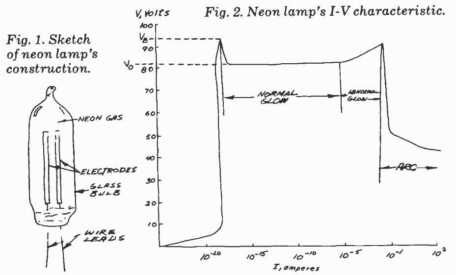
An outline view of a typical glow lamp is shown in Fig. 1. Few electronic components are as structurally simple - a glow lamp consists merely of a gas-filled bulb and a pair of electrodes to which wire leads have been attached. Normally, the resistance of the gas between the two electrodes is so high that the lamp can be considered an open circuit. But when the voltage across the lamp is raised to the critical initial breakdown voltage, the gas ionizes and becomes highly conductive. The ionized gas glows with a characteristic color. Neon, the most common filler gas, glows orange. Argon, which is sometimes used, has a blue glow.

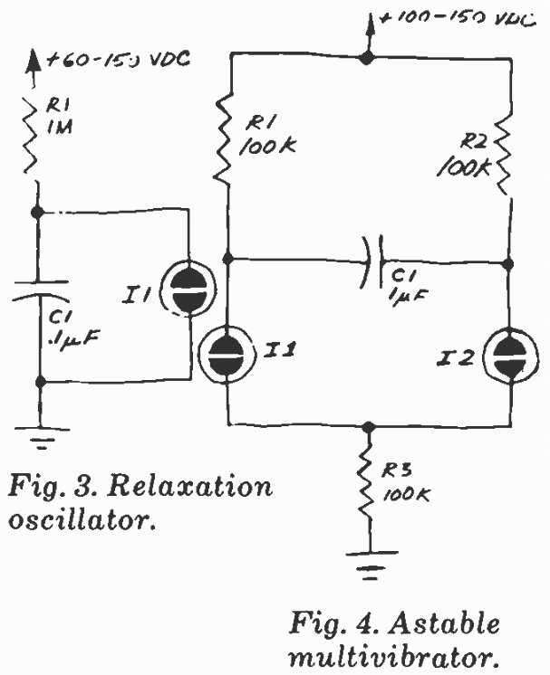
Figure 2 shows the I-V characteristics of a typical neón bulb. Until the breakdown voltage VB is reached, current through the lamp is very small. (This voltage will vary between 55 and 150 volts for commercially available bulbs.) When the bulb fires, it enters the normal glow region of its I-V curve. In this region, the soft, luminous glow is confined to the negative electrode, and the glow area increases directly with lamp current. The voltage-regulating properties of the neon lamp are self-evident in Fig. 2. A nearly constant voltage drop VO exists across the lamp even though the current varies over a wide range.

When current is so high that the entire surface of the electrode ís covered by the glow, the voltage across the lamp rises. The neon lamp has then entered the abnormal glow region. If lamp current further increases, the lamp is operating in the arc region. Here, the voltage across the lamp drops and the orange-colored discharge becomes a bright point of bluish-white light centered on the cathode (negative) electrode. Prolonged operation ih the abnormal glow region, and even a brief incursion into the arc region will destroy the lamp.

Although neon lamps operate at fairly high voltages, they consume small amounts of power, and most commercial devices are rated at a continuous current of 0.1 to 10 mA.

Figs 1 and 2

Some Precautions. Neon glow lamps are simple to use, but you should be aware of a few special restrictions. First, these lamps are subiect to what is called the dark effect. That is, ionization of the gas is much more easily accomplished in the presence of ambient light. In total darkness, the glow lamp operates erratically, and its breakdown voltage increases significantly. To overcome this problem, many neon lamps contain a minute amount of radioactive gas, which stimulates ionization.

A second operating restriction is the necessity to avoid excessive operating voltages. Too much voltage will cause the lamp to operate in the abnormal glow or arc region. The third consideration is current limiting. It is necessary to place a resistor in series with a continuously operated glow lamp. This ballast resistor limits the current through the lamp to a safe value. If we assume that an ionized glow lamp has practically no resistance but a voltage drop of 80 volts, Ohm's and Kirchoff's Laws dictate that a 100,000-ohm ballast resistor will allow a safe 200 μA to flow through a glow lamp connected to a 100-volt dc source.

Glow Lamp Circuits. Now that we've covered some of the basics of glow lamp operation, let's examine several practical circuits. You can use the miniature dc-dc converter described in last month's column or a pair of 67 1/2-volt batteries connected in series as a power supply.

Figs 3 and 4

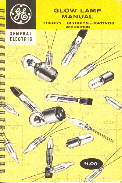
The simplest circuit is the glow-lamp relaxation oscillator shown in Fig. 3. In operation, Cl charges through R1 until the breakdown voltage of the neon lamp is reached. At that point, Cl discharges through the lamp and produces an orange flash. When the voltage across Cl drops below the voltage necessary to keep the lamp conducting, the lamp goes dark. Then Cl begins to charge and the cycle repeats.

To see the glow-lamp flash you will have to use at least a 1-megohm resistor. Otherwise the flash rate will be faster than the 18 pulses per second discernible by the human eye and the lamp will appear continuously on. Also, use 200-volt capacitors in this and the following circuits because of the high voltages present.

You can connect an oscilloscope across C1 to verify that the circuit is oscillating if you choose to operate it at audio frequencies. Alternatively, you can connect an 8-ohm speaker between the glow lamp and ground or place the circuit near a radio to actually hear the oscillation frequency or its harmonics.

If you're familiar with neon-lamp relaxation oscillators, you probably know that several circuits like the one shown in Fig. 3 can be cascaded to produce a pseudo-random flashing effect. These circuits are often seen flashing away in electronics labs and are called "do-noth ing boxes" or "idiot lights."

An astable multivibrator made from two glow lamps is shown in Fig. 4. If we assume I1 has a lower turn-on voltage than I2, I1 will turn on first after power has been applied. This permits Cl to charge through R2 and I1. When the voltage across Cl exceeds the turn-on voltage of I2, I2 turns on and I1 turns off. Now Cl charges through R1 and I2 until its charge fires I1. Lamp I2 then turns off, Cl begins charging through R2, and the cycle repeats. The circuits described here incorporate a relaxation oscillator, and you can easily vary the repetition rates of the oscillators by altering the values for the resistor and capacitor which, together with the lamp, form the oscillator (R1 and Cl in Fig. 3, etc.). Higher values of resistance or capacitance will slow the repetition rate. But try to keep R1 above 100,000 ohms, and Cl below 1μF.

If you do experiment with any of these circuits, be sure to observe standard safety precautions. Even a 67 1/2-volt battery can deliver a sharp shock, and if the shock itself doesn't affect you, the resulting reflex action may dash your wrist or elbow into your work bench or chair. For best results and optimum safety, stick to batteries or miniature high-voltage power supplies like the one described in last month's column. If you must use line power, never operate a glow-lamp circuit from the ac line without using a 1:1 isolation transformer.

GENERAL ELECTRIC CIRCUITS
The following pages are scanned from the GE Glow Lamp Manual, 2nd Edition, dated 1965.

A Glow Lamp Ring Counter

A glow lamp ring counter capable of counting at rates up to several hundred pulses per second was first reported by Manley and Buckley. A modified version of this ring counter is shown in Figure 3.26 for a count-of-six counter. Any even number may be counted by adding additional pairs of glow lamp-semiconductor diode combinations.


[Medium]   [Large]
(Pages 61 and 62)

 
Memory Circuits

The properties of the glow lamp make it a very suitable device for several different types of storage or memory circuits. One such memory circuit is shown in Figure 3.28.


[Medium]   [Large]
(Pages 63 and 64)

 
Memory Circuit (con't)

Another type of memory circuit which is becoming quite popular employs a glow lamp in conjunction with a photoconductor or other type of photosensitive device. The photoconductor has a decreasing resistance as the incident illumination is increased. Figure 3.29 shows one manner in which a glow lamp and photoconductor may be used as a memory circuit.


[Medium]   [Large]
(Pages 65 and 66)


Comments to Webmaster

Click here for the Home page.
Click here for the Wanted page.

Updated May 21, 2020