The basic concept of a delay-line memory consists of inserting an information pattern into a path which contains delay. If the end of the delay path is connected back to the beginning through amplifying and timing circuits, a closed loop is formed allowing for recirculation of the information pattern. A delay-line memory resembles the human device of repeating a telephone number to one's self from the time it is found in the directory until it has been dialed. The delay medium should slow the propagation rate of the information sufficiently so that the size of the storage equipment for a large number of pulses be within reason.
Many different media have been suggested for delay-line memory systems. Some delay lines transmit the information pattern acoustically and some electromagnetically. Both mercury and quartz are examples of acoustical delay-line media, with mercury probably receiving the widest use so far. Electrical delay lines, eithree distributed paramter or lumped parameter, are examples of electromagnetic delay lines. Neither type is as efficient spacewise as the acoustic line.

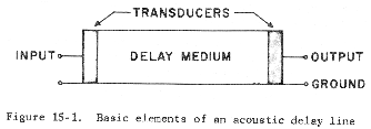
A simple acoustic delay line consists of a delay medium and two transducers; this is shown in Figure 15-1. The transducers convert electrical signals into mechanical stress, or vice versa, by the piezoelectric effect. The mechanical stress applied to the delay medium travels through a prescribed path as an acoustic wave which in turn applies a mechanical stress on the output transducer to reproduce the electrical signal.

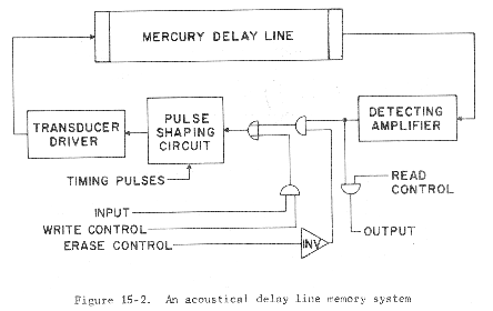
Figure 15-2 shows a block diagram of one channel of the UNIVAC memory system. This memory system consists of one hundred channels, with each channel capable of holding ten 91-bit words or approximately 1000 pulses per channel. The loop is closed through the recirculation amplifier which contains amplifying, timing, and pulse reshaping circuits. Also included in this circuitry are the gates by means of which data are read in and read out or cleared (erased).
Reading and writing in a delay-line memory system is accomplished by an address circuit whose function is to identify each pulse period of the recycling memory pattern. In its simplest form, the address circuit may be thought of as a counter which counts pulse periods under control of the synchronizing timing pulses of the system. In this way the delay period is broken up into a number of pulse periods, each pulse period being identified by a particular count or address as indicated by the counter. After each circulation time of the memory, the counter is reset. Thus to read or write in a particular address, all that is necessary is to wait until the counter indicates the correct address whereupon the read or write gate, as the case may be, is operated. Besides indicating where in the circulation cycle the stored work is located, the identity of the proper delay line is also required.
The use of any delay-line memory system usually makes time sharing of the recirculation circuits impractical. Other disadvantages of the delay-line memory systems are the access time (the maximum access time being the length of the delay) which is characteristic of a memory system with a cyclic access rather than random access, and the amount of terminal equipment required. Making longer channels amortizes the terminal equipment over more memory, but increases the access time. In the event of power failure, the stored information is lost.