 Build R-E's
IC Digital Clocks
Build R-E's
IC Digital Clocks
Decorators wild! Pick your style, build the kind of clock you like best
by ED LORD
Building a digital clock is a great project with a rewarding climax. The 6-digit clock described here, besides being a great conversation piece, will make an outstanding piece of furniture for your desk or living room.
Digital clocks, list most accurate instruments, are expensive. However, since the advent of IC's and with advances in the state-of-the-art a digital clock can be a reality. This clock can be build for about $250.00 with six digits as described here. For the more economically minded, a four digit model can be made for considerably less, leaving out IC10 and IC8, V5 and V6. A little scavanging (like we all seem to be masters at), and a well-stocked scrap barrel can also do wonders in saving the bank roll.
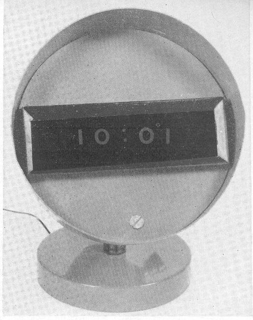
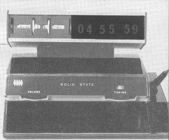 The Nixie tube readouts can be remoted. This gives the
builder the utmost in freedom of design. Two of the clocks on
the cover are good examples of this technique. The black
desk-set clock was originally a desk radio that was redesigned
and converted into a six-digit clock. Its electronics are
packaged separately and can be unobtrusively secured to the side
of a desk. The cramped space dictated the use of rectangular
Nixie tubes type B.
The Nixie tube readouts can be remoted. This gives the
builder the utmost in freedom of design. Two of the clocks on
the cover are good examples of this technique. The black
desk-set clock was originally a desk radio that was redesigned
and converted into a six-digit clock. Its electronics are
packaged separately and can be unobtrusively secured to the side
of a desk. The cramped space dictated the use of rectangular
Nixie tubes type B.
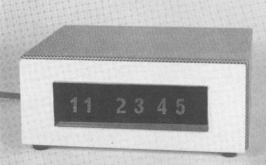
The red clock started life as a bed lamp. After a trip to a junk shop it was resurrected and now is a four-digit clock with the electronics mounted behind the bezel. A friend of mine packaged the readout for his clock in a roll-on deodorant can and mounted it on the neck-piece of a broken goose neck lamp. He packaged the electronics in the base. It's a real Buck Rogers masterpiece that fits well into his modern home furnishings. A trip through a second-hand junk store or your local drug store will give you many great ideas for a great new and original clock design.
 The two most important ingredients in my lock, the IC's and
readouts, were chosen very carefully. THe IC's are the
heart of the clock I was especially careful here. I use
SN7490N counters and SN7441N Nixie tube drivers made by
Texas Instruments. They have good noise immunity for a 5V IC
and can be counted on for reliability and long life. The
Burroughs B-5750S Nixie tubes were chosen because they were
originally designed for a calculator market as a high pressure
tube and they are the best available when one digit must remain
on for any length of time. (The 0 in the first digit is on
for 9 hours at a time, the 1 is on for 3 hours.)
The two most important ingredients in my lock, the IC's and
readouts, were chosen very carefully. THe IC's are the
heart of the clock I was especially careful here. I use
SN7490N counters and SN7441N Nixie tube drivers made by
Texas Instruments. They have good noise immunity for a 5V IC
and can be counted on for reliability and long life. The
Burroughs B-5750S Nixie tubes were chosen because they were
originally designed for a calculator market as a high pressure
tube and they are the best available when one digit must remain
on for any length of time. (The 0 in the first digit is on
for 9 hours at a time, the 1 is on for 3 hours.)
How it works
Clock operation can be broken down into basic subsystems - the
13 o'clock reset circuit, the basic counting circcuits,
the timing circuits and, of course, the power supply.
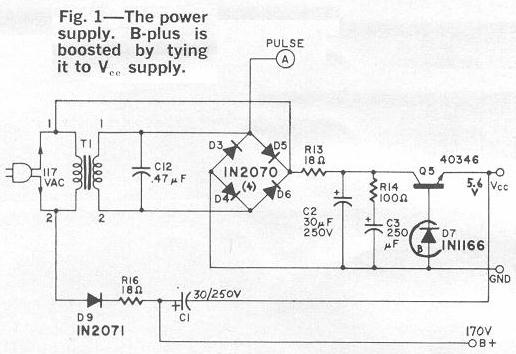 The power supply is a simple half-wave rectifier that provides
pulse input tot he timing circuits. Also provision is made through
transistor Q5 and the 6.3V Zener diode for 5.6 volt Vcc.
Also B+ is tapped from the 117 Vac input and converted to
+170 Vdc by the voltage booster D9, R16, and C1. Capacitor C12
is installed across the secondary to remove line transients on the
input pulse (see Fig. 1).
The power supply is a simple half-wave rectifier that provides
pulse input tot he timing circuits. Also provision is made through
transistor Q5 and the 6.3V Zener diode for 5.6 volt Vcc.
Also B+ is tapped from the 117 Vac input and converted to
+170 Vdc by the voltage booster D9, R16, and C1. Capacitor C12
is installed across the secondary to remove line transients on the
input pulse (see Fig. 1).
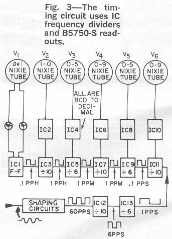
Timing circuit
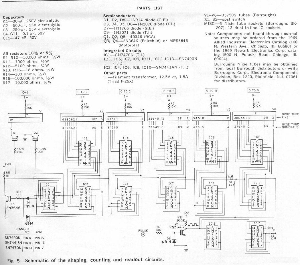
 The half-wave 60-Hz input to the timing circuit is shaped to
positive square wave pulses by Q4 and associated circuitry
(see Fig. 5 and Fig. 3). The resulting 60-Hz square wave is
applied at pin 14 of the divide by 10 counter, IC 12.
These counters count on the negative going side of the square
wave. Output from IC 12, a 6 pps square wave, is applied to
pin 14 of IC 13, a divide by 6 counter. IC 13's output is a 1 pps
square wave which is applied to pin 14 of IC 11. The counter
is wired in a divide by 10 configuration. It resets when 9 is
displayed and the square wave goes negative. The counter outputs
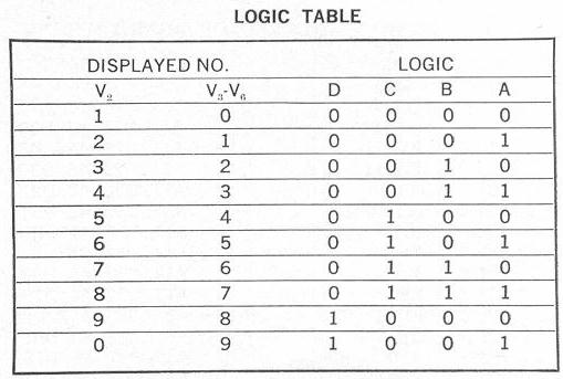
standard 8421 BCD which is applied to readout driver IC 10.
Basically IC 10 is a BDC to decimal decoder driver with output
transistors that can handle enough current to directly drive the
Nixie tube. It provides the first seconds digit for a 0 through 9
readout. When the 9 is displayed on the first Nixie tube, V6,
codes D and A (see logic table) go high as the counter resets to
zero and D goes low. IC 9, the divide by six counter, is pulsed.
The BCD output of this counter is decoded and displayed on
V5, the second significant digit in the clock. This cycle repeats
with IC 9 counting once for each 10 counts of IC 11.
The half-wave 60-Hz input to the timing circuit is shaped to
positive square wave pulses by Q4 and associated circuitry
(see Fig. 5 and Fig. 3). The resulting 60-Hz square wave is
applied at pin 14 of the divide by 10 counter, IC 12.
These counters count on the negative going side of the square
wave. Output from IC 12, a 6 pps square wave, is applied to
pin 14 of IC 13, a divide by 6 counter. IC 13's output is a 1 pps
square wave which is applied to pin 14 of IC 11. The counter
is wired in a divide by 10 configuration. It resets when 9 is
displayed and the square wave goes negative. The counter outputs
standard 8421 BCD which is applied to readout driver IC 10.
Basically IC 10 is a BDC to decimal decoder driver with output
transistors that can handle enough current to directly drive the
Nixie tube. It provides the first seconds digit for a 0 through 9
readout. When the 9 is displayed on the first Nixie tube, V6,
codes D and A (see logic table) go high as the counter resets to
zero and D goes low. IC 9, the divide by six counter, is pulsed.
The BCD output of this counter is decoded and displayed on
V5, the second significant digit in the clock. This cycle repeats
with IC 9 counting once for each 10 counts of IC 11.
 When IC 9 reaches 5, logic codes C and A are high.
C (pin 8) is connected to the input pin (14) of IC 7 which
is the first digit of the "minutes" section of the clock.
IC 7 and its associated decoder driver, IC 6, are wired in
the same configuration as the 0-9 indicator in the seconds
second (IC 11, IC 10 and V6). Operating IC 7 and IC 6 cause
0-9 minutes to be displayed on V4. When 9 comes up, logic D
and A are high and cause an input to be felt at pin 14 of
IC 5, the 0-5 portion of the minutes indicator. (Remember,
the count occurs as the pulse goes toward the negative in
these counters.) The minutes 0-5 is wired exactly the same
as the seconds 0-5 section and operates in a similar manner.
When 5 is displayed on V3 and logic C and A is high, the C
is felt on pin 14 of the divide by 10 counter, IC 3. This
counter counts once each time IC 5 resets and is wired
similarly to IC 7 and IC 11 with the one important difference
described in the next paragraph.
When IC 9 reaches 5, logic codes C and A are high.
C (pin 8) is connected to the input pin (14) of IC 7 which
is the first digit of the "minutes" section of the clock.
IC 7 and its associated decoder driver, IC 6, are wired in
the same configuration as the 0-9 indicator in the seconds
second (IC 11, IC 10 and V6). Operating IC 7 and IC 6 cause
0-9 minutes to be displayed on V4. When 9 comes up, logic D
and A are high and cause an input to be felt at pin 14 of
IC 5, the 0-5 portion of the minutes indicator. (Remember,
the count occurs as the pulse goes toward the negative in
these counters.) The minutes 0-5 is wired exactly the same
as the seconds 0-5 section and operates in a similar manner.
When 5 is displayed on V3 and logic C and A is high, the C
is felt on pin 14 of the divide by 10 counter, IC 3. This
counter counts once each time IC 5 resets and is wired
similarly to IC 7 and IC 11 with the one important difference
described in the next paragraph.
Reset circuit
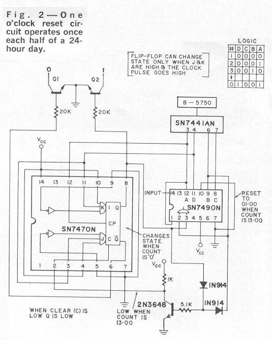 The problem in the hours circuit is that V2 must count from
1 o'clock to zero as V1 indicates 1 for 10 o'clock. V2 must
then count 1 and 2, then reset to 1 o'clock. This is done
by wiring decoder driver IC 2 so it thinks it is displaying a
0 on V2 when it is actually displaying a 1. When it thinks it
is displaying a 1, it actually showing a 2 and so on until it
displays a 0 which the decoder driver thinks is a 9. After the
zero is displayed the counter resets to zero, logic D and A
are high causing flip flop IC 1 to change state and turn off
Q1 and turn on Q2 which extinguishes the 0 displayed on V1 and
lights the 1. (See Fig. 2).
The problem in the hours circuit is that V2 must count from
1 o'clock to zero as V1 indicates 1 for 10 o'clock. V2 must
then count 1 and 2, then reset to 1 o'clock. This is done
by wiring decoder driver IC 2 so it thinks it is displaying a
0 on V2 when it is actually displaying a 1. When it thinks it
is displaying a 1, it actually showing a 2 and so on until it
displays a 0 which the decoder driver thinks is a 9. After the
zero is displayed the counter resets to zero, logic D and A
are high causing flip flop IC 1 to change state and turn off
Q1 and turn on Q2 which extinguishes the 0 displayed on V1 and
lights the 1. (See Fig. 2).
As V2 counts to a 3 (would appear as 13 on hours indicators V1 and V2) logic B goes high which causes pin 2 of IC 2 to go high. Simultaneously current flow through D2 is routed from B to E of Q3 causing pin 2 of IC 1 to go low and reset the flip flop. The result is that 0 lights on V1, pins 2 and 3 in IC 3 are high and IC 3 resets to 1. The count cycle 1-0 begins again for the second half of the 24-hour day.
Construction tips
Assembling this project can be extremely complicated because of
the number of ICs and associated components. To simplify
procedures a bit I strongly recommend using IC sockets. There
are two reasons. First and foremost, if you apply too much
heat to an IC lead, chances are you'll zap the IC and when you
consider you will be soldering upwards of 180 IC leads your odds
are short on a perfect job. Second and of paramount importance
from an operational standpoint, is the fact that IC characteristics
will vary somewhat and a quick switch of ICs may solve a problem
that otherwise might have to be corrected by a value change in
the associated circuitry.
Tables are provided for both component to component and point-to-point Vector board wiring. Either method is effective. However, if you are not an experienced builder with many "projects" under your belt I'd suggest using the Vector board chart as it is the simplest and most straightforward.
Follow the steps in the order listed and you will be home free after a few evenings of enjoyable labor.
[The remainder of the article consists of step-by-step instructions for assembly and a table of Vector board coordinates. See the individual page scans if you're interested in actually building this clock as-described.]
Click here
for the Radio-Electronics article page.
Click here
for the Nixie page.
Click here
for the main page.