 Nixies* are easy to work with once
you understand them. And they're not too complicated.
Nixies* are easy to work with once
you understand them. And they're not too complicated.
HOW DIGITAL READOUTS WORK
Nixies* are easy to work with once
you understand them. And they're not too complicated.
by GEORGE FLYNN
If you've ever seen a digital voltmeter or a frequency counter you've probably seen Nixie tubes, because their use in digital instruments of all kinds has become widespread. Several other types of readout tubes are also used in some instruments, but more Nixies and Nixie-type devices are used than all other kinds put together and multiplied by ten. And for a very simple reason - the Nixie does a good job of displaying numbers and it does it cheaper than anything else.
Since Nixies seem certain to be around for a long time, and since anybody who associates with electronic types is bound to cross lances with this baby some time or other, it worth taking a good hard look at what the thing really is. What does it do? How does it work? What makes it act up?
The basic job of any readout tube is to display numbers and/or letters and other symbols. The numbers, however, are more significant than letters in many applications, and thus a great deal of the art of letting machines talk to man deals primarily with numbers, plus a few symbols. Nixie-type devices, in particular, have been developed primarily to display numbers rather than letters.
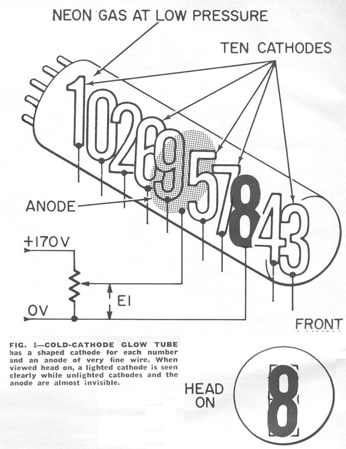
The typical Nixie is a cold-cathode gas glow tube that has an anode and ten cathodes, as in Fig. 1. (Variations, including tubes with plus sign and minus sign, are also available). Each cathode has an activated surface that allows it to emit electrons readily. Connect a voltage source to the anode and to any one cathode - leave the others open - and raise the voltage slowly. At a relatively low voltage the cathode will begin to glow over a small portion of its surface. Continue raising the voltage and the glow will spread until the whole cathode is lit and a number - 0 through 9 depending on which cathode you latched on to - will be clearly visible, even from many feet away.
If the voltage is raised still further, the glow will creep down from the activated cathode surface and along the connecting lead and on to the socket pin. When this happens, you'll know you've gone too far. Lower the voltage until only the cathode area glows. You are now within the correct operating region for the tube.
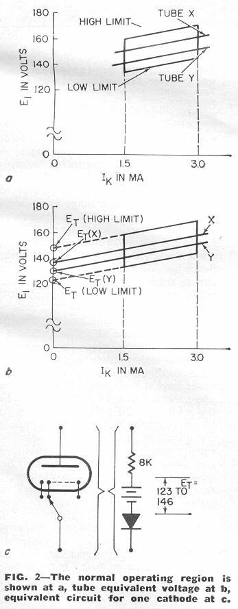 Careful experiments with the current and voltage characteristics
of the Nixie have established the normal operating region as
shown by Fig. 2-a. The drawing allows for all the variables -
element spacing, cathode activity, gas pressure, etc. - that
cause individual tubes and individual cathodes within the same
tube to differ slightly from each other. The minimum current
needed to completely light a cathode of a Type B5991 Nixie
(one of the most common varieties) is 1.5 mA. The maximum
current for complete lighting but without creeping glow is 3 mA.
When a cathode is drawing 1.5 mA, the voltage cross the tube -
E1 in Fig. 1 - is a function of the specific tube
and specific cathodes and can be as low as 135 volts, but will
not be more than 159 volts. When a cathode is drawing 3 mA,
E1 again depends on the specific tube and cathode and
will range from 144 to 168 volts. Two other electrical
characteristics of the tube are worth noting. Operating the
device with the voltage slightly high will not cause any
smoke, but you may see the creeping glow. Operating at
slightly low voltage can lead to only partial lighting of the
cathode. Not good but not always awful.
Careful experiments with the current and voltage characteristics
of the Nixie have established the normal operating region as
shown by Fig. 2-a. The drawing allows for all the variables -
element spacing, cathode activity, gas pressure, etc. - that
cause individual tubes and individual cathodes within the same
tube to differ slightly from each other. The minimum current
needed to completely light a cathode of a Type B5991 Nixie
(one of the most common varieties) is 1.5 mA. The maximum
current for complete lighting but without creeping glow is 3 mA.
When a cathode is drawing 1.5 mA, the voltage cross the tube -
E1 in Fig. 1 - is a function of the specific tube
and specific cathodes and can be as low as 135 volts, but will
not be more than 159 volts. When a cathode is drawing 3 mA,
E1 again depends on the specific tube and cathode and
will range from 144 to 168 volts. Two other electrical
characteristics of the tube are worth noting. Operating the
device with the voltage slightly high will not cause any
smoke, but you may see the creeping glow. Operating at
slightly low voltage can lead to only partial lighting of the
cathode. Not good but not always awful.
Now a circuit designer working with Nixie indicators likes to run the devices right in the middle of their normal operating range; the middle is 2.25 mA with the anode riding at about 155 volts. Then, if the supply voltage varies, but not too much, the tube will still operate satisfactorily.
Note in Fig. 2-a that the operating curves are straight but that the voltage drop across the tube increases as cathode current increases. Any specific tube, such as tube X or Y, will have a curve parallel to the high and low limits. Note in Fig. 2-b that if you extend the operating curves to the left until cathode current is reduced to zero, you intersect the voltage axis at about 123 volts for the low-limit line and at about 146 volts for the high limit. Individual tubes will vary between these limits. Thus you have to buck out anywhere from 123 to 146 volts before the tube conducts significantly.
The fact that the operating curve for a given tube is a straight line tells us the device is acting like a resistor - once it starts conducting. These characteristics are duplicated by the equivalent circuit of Fig. 2-c; a resistor in series with a perfect battery and a perfect diode. The circuit applies only to the normal operating region of the tube - that is, when it is conducting 1.5 to 3.0 mA. When the tube is operated below 1.5 mA, the equivalent series resistance begins to increase and is nonlinear. The actual V-I curves also have a negative-resistance region when conduction begins.
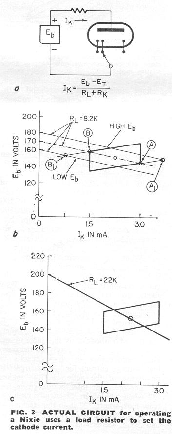 Once the operating current and voltage have been set, the
operating circuit can be designed. Fig. 3-a is a typical
circuit that consists of a voltage source, a current-limiting
resistor and one cathode of the indicator tube. Point A on
the operating curve, Fig. 3-b, represents a low-voltage cathode
being run at high current, which point B represents a high-voltage
cathode running at low current. Drawing a load line through
A and B and extending it to intersect the voltage axis gives
minimum Eb and associated RL: minimum
Eb is 170 volts, and RL - from the
slope of the load line - is 8200 ohms. With these values,
and since the operating point for any cathode is at the
intersection of its operative curve and the load line, most
cathodes will operate close to the optimum current of 2.25 mA,
and only an occasional cathode will operate near A
or B. But if Eb should sag to 160 volts,
as shown, a cathode that normally operates at the point
B will now operate at B1, or at
a current of only about 0.75 mA. Partial glow.
Once the operating current and voltage have been set, the
operating circuit can be designed. Fig. 3-a is a typical
circuit that consists of a voltage source, a current-limiting
resistor and one cathode of the indicator tube. Point A on
the operating curve, Fig. 3-b, represents a low-voltage cathode
being run at high current, which point B represents a high-voltage
cathode running at low current. Drawing a load line through
A and B and extending it to intersect the voltage axis gives
minimum Eb and associated RL: minimum
Eb is 170 volts, and RL - from the
slope of the load line - is 8200 ohms. With these values,
and since the operating point for any cathode is at the
intersection of its operative curve and the load line, most
cathodes will operate close to the optimum current of 2.25 mA,
and only an occasional cathode will operate near A
or B. But if Eb should sag to 160 volts,
as shown, a cathode that normally operates at the point
B will now operate at B1, or at
a current of only about 0.75 mA. Partial glow.
If, on the other hand, Eb should rise to 180, a cathode that normally operates at point A will be shifted out to point A1, to a current of about 3.6 mA and into creeping glow.
To avoid this high sensitivity to changes in Eb, many Nixies are operated with Eb close to 200 volts rather than at 170 volts. Draw the load line, Fig. 3-c, from the actual Eb through the center (2.25 mA) of the operating curves. The slope of the line gives RL of 22,000 ohms. With these values, the circuit will tolerate a change of Eb of about +/- 5% (10 volts) without the load line during out of the operating region.
But RL should be set close to its calculated values. As RL changes, the slope of the load line changes, and this again can lead to either partial or creeping glow. Current flow for any set of conditions can be calculated from the equation given in Fig. 3-a.
Partial glow
By now you may have decided that a Nixie is nothing more than
a glorified neon indicator tube. You are partly right but
only because we've been talking about energizing just one cathode
at a time and leaving the other cathodes open. Since the open
cathodes can't draw any current, they can't act up very much.
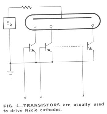 Put a Nixie into a circuit, however, and you usually want to
drive it with a transistor, not a rotary switch. The circuit
shown in Fig. 4 is recommended by manufacturers of the
indicators and uses an npn transistor for each cathode.
When one of the transistors is turned on, it becomes a low
resistance and grounds its associated cathode, turning it
on. The other transistors are off and present a very high
impedance to the flow of current from anode to cathode
and thereby to ground.
Put a Nixie into a circuit, however, and you usually want to
drive it with a transistor, not a rotary switch. The circuit
shown in Fig. 4 is recommended by manufacturers of the
indicators and uses an npn transistor for each cathode.
When one of the transistors is turned on, it becomes a low
resistance and grounds its associated cathode, turning it
on. The other transistors are off and present a very high
impedance to the flow of current from anode to cathode
and thereby to ground.
Assume that the transistor for the cathode of numeral "1" is turned on, and "1" is lit. What is the voltage at the collectors of the off transistors - such as for numeral "0"?
If the transistors were perfect, they would act like infinite resistances and no cathode currents would flow unless the transistor was on. But transistors are not perfect and there is a leakage current from the off cathodes through the off transistors.
The magnitude of the off current is a function primarily of the leakage current characteristic of the transistor, while the voltage at the off cathodes is determined by the collector breakdown voltage of the transistor. What the circuit requires is a transistor with low leakage current and high collector breakdown voltage.
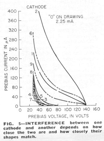 Extensive experiments have been carried out to determine what
levels of leakage current and voltage can be tolerated before
objectionable glow is generated by numerals that are supposed
to completely off. Figure 5 shows typical leakage current
flows through off cathodes as a function of cathode voltage,
which is called the "prebias voltage". Numeral "0" is on, which
means that its cathode is grounded (or has on equivalent
prebias voltage of zero) and current through "0" cathode is
2.25 mA. Now look at the curve for cathode "2". When its
prebias voltage is 140 volts, and if Eb is 170,
then the voltage available to "2" is 170 - 140 or 30 volts,
and the current flow is way down around zero.
Extensive experiments have been carried out to determine what
levels of leakage current and voltage can be tolerated before
objectionable glow is generated by numerals that are supposed
to completely off. Figure 5 shows typical leakage current
flows through off cathodes as a function of cathode voltage,
which is called the "prebias voltage". Numeral "0" is on, which
means that its cathode is grounded (or has on equivalent
prebias voltage of zero) and current through "0" cathode is
2.25 mA. Now look at the curve for cathode "2". When its
prebias voltage is 140 volts, and if Eb is 170,
then the voltage available to "2" is 170 - 140 or 30 volts,
and the current flow is way down around zero.
Let the voltage on "2" drop to 100 and the current rises to well over 100 microamperes. As the prebias voltage drops further, leakage current continues to increase until eventually "2" will start to turn on.
When you perform the same tests on cathode 6 ("0" still on) you get less leakage current but the shape of the curve is approximately the same. Why should you get a different current flow for "6" than for "2"? Look at the actual arrangement or stacking of the cathodes as indicated in Fig. 1. Cathode "2" is physically close to cathode "0". Further, the top of cathode 2 is the same shape as the top of 0: the result of nearness plus conformance of shape result in high leakage current for "2" when "0" is on - some of the action at "0" makes "2" nervous. But look at the curve for "3" when "0" is on: practically nothing. Now look where "3" is in the stacking - it's as far away from "0" as it can be and it's on the other side of the anode as well.
If you perform the same tests with the rest of the cathodes, you get similar curves. When "8" is on, it has more effect on 4 and 7 than on 0 and 1.
All right, you say, so you get a little leakage - who cares? We now go to the second set of experiments, which try to answer the question, "How much leakage current causes an objectionable glow from cathodes that are supposed to be off?"
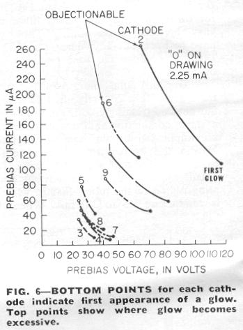 Fig. 6 shows how some observers judged the effects of leakage.
Again, cathode "0" is on and the others are off. Based on the
leakage characteristics for "0" (Fig. 5), we know cathode "2"
is going to bomb out first if anything does. Observers report
that barely perceptible glow appears on "2" when the leakage
is about 110 microamperes, while its associated prebias voltage
is 120 V; when the prebias drops to 70V, the leakage is about
250 microamperes and the glow on "2" is obvious and
"probably objectionable".
Fig. 6 shows how some observers judged the effects of leakage.
Again, cathode "0" is on and the others are off. Based on the
leakage characteristics for "0" (Fig. 5), we know cathode "2"
is going to bomb out first if anything does. Observers report
that barely perceptible glow appears on "2" when the leakage
is about 110 microamperes, while its associated prebias voltage
is 120 V; when the prebias drops to 70V, the leakage is about
250 microamperes and the glow on "2" is obvious and
"probably objectionable".
But look at cathode "3". To get a glow at all you have to take the prebias down to 35 V - it's almost turned on. But as soon as "3" does start to leak, it really acts up - it only needs about 35 microamperes to become a clown.
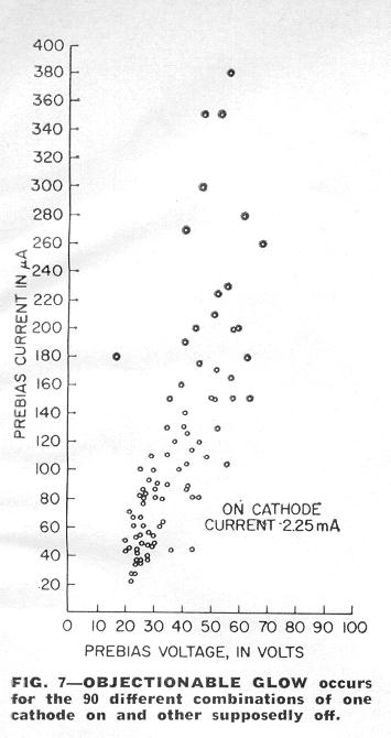 Turn the 10 cathodes on one at a time and measure all other
cathodes to find objectionable glow limits and you come up
with 90 dots as shown in Fig. 7. According to this drawing
you will never have a bad glow if you keep leakage current
below 20 microamperes, or if you held the prebias at 70 volts
and above. And if you can hold leakage below 2 microamperes,
(at all operating temperatures), says Burroughs, you won't
ever get a noticeable glow even for sensitive combinations
(such as "0" on and 3 at a prebias of 35). And for most
tubes, 60 volts prebias - instead of 70 - is good enough.
Turn the 10 cathodes on one at a time and measure all other
cathodes to find objectionable glow limits and you come up
with 90 dots as shown in Fig. 7. According to this drawing
you will never have a bad glow if you keep leakage current
below 20 microamperes, or if you held the prebias at 70 volts
and above. And if you can hold leakage below 2 microamperes,
(at all operating temperatures), says Burroughs, you won't
ever get a noticeable glow even for sensitive combinations
(such as "0" on and 3 at a prebias of 35). And for most
tubes, 60 volts prebias - instead of 70 - is good enough.
One situation which almost defies analysis is, "What happens when one cathode is on and two or more start glowing?" You can expect that two little glows (or three or four) may be worse than one little glow but probably better than one big glow. Play it safe and keep the glows down.
Ionizing peculiarities
Neon indicator tubes must be treated with due respect to the
limitations of cold-cathode devices. Many of the limitations
are not serious - thatis, they are easily overcome - but
they can cause a lot of tree-climbing or head-bashing-against-the-wall
action if not understood.
One of the major variables of the neon indicator tube is turn-on time, which is the same as ionization time. Cold-cathode devices depend upon external radiation for initial ionization. You can apply rated voltage between anode and cathode and wait, but nothing will happen until a cosmic ray or an energetic particle from an atom undergoing radiocative decay strikes the cathode and starts the electrons flowing. Once started, the ionization is self-sustaining through the action of the electrons jumping around.
The starting incident does not need to be an energetic particle. Ordinary light - natural or man made, and bright enough to allow easy viewing - provides enough energy at the cathode surface to insure ionization under most conditions. Ionization can also be made more certain by applying increased voltage across the tube (without exceeding ratings) or by applying the voltage fast rather than slow. In addition, ionization time is affected by how long the tube has been sitting around without being turned on. The longer it's been inactive the lazier it is.
Burroughs Corp. says that ionization time will almost always be less than 100 microseconds in normal applications and with usual light levels. But the variations in the characteristics of cold-cathode tubes, plus the variations in local lighting and background radiation, are such that ionization time may be as short as 1 microsecond or as long as several seconds.
What happens when you want to use a Nixie in a coal mine in total darkness? In the case it may be more a question of what will not happen - the indicator may never turn on. But there's really no need for this type foul-up if it is known beforehand that the tube is going to be used in absolute darkness. The manufacturers have developed a special tube that contains a small amount of radioactive Krypton 85 gas, which is relatively inactive but emits a particle sufficiently often to cause the tube to turn on within 50 msec usually, and within 1 sec practically always.
How to dim
Cold-cathode indicator tubes are bright enough for use in
fairly strong light. Sometimes, however, the tubes are
too bright - as in radar rooms and aircraft cockpits - and
dimming methods are needed. Reducing the voltage across the
tube may produce slight dimming but runs into the problem of
failing to completely light some cathodes.
The simplest way to reduce brightness is to use an optical filter in front of the tube. If continuously variable brightness control is not needed, optical filters can work well. Polaroid filters are available, in fact, that reduce brightness and reflections at the same time.
If electrical control of brightness is needed, two techniques are available. In the first method a cathode is turned on for awhile, then off, then on again, etc, at a regular rate or frequency. If the fixed frequency is 50 Hz or higher, the tube appears to be on continuously, and the apparent brightness is a function of the on time to off time - the duty cycle. The maximum duty cycle is 1.000, or continuously on. The minimum duty cycle is determined essentially by the ionization time - 100 microseconds for reliable operation - which gives an on-to-off ratio of 1 part in 200, or a duty cycle of 0.005 (or 0.5%).
The second way to control brightness also uses the concept of duty cycle but in this case the on-time of the cathode is fixed - again, 100 microseconds minimum - as the period between on-pulses is varied. If the on pulses arrive one every 100 microseconds (or whatever the on time is set to) the tube is on continuously, the duty cycle is 1, and brightness is maximum. If only 50 on-pulses per second (minimum rate for flicker-free viewing) are applied, the duty cycle is 0.005, (with 100 microsecond on-time) and brightness is way down.
Both methods give the same results but the fixed frequency method causes less power dissipation - because less switching is required - in the drive circuits. Usually the on-pulses are applied via the anode. The tubes are often driven from a 200-volt supply and the anode voltage only has to be lowered to below 110 volts to turn the tube off. Anode control also eases the breakdown voltage requirements of the drive transistors in the cathode circuits.
Do you remember the story about the little girl who read a book about alligators and when her teacher asked her how she liked it, said: "This book told me more about alligators than I wanted to know."
While more could be said about the cold-cathode indicator tube - and about its competitors who are fighting for a chance to be seen - we've about run out of space.
One recent development should be mentioned. The tubes are usually driven by combination decoding/driving circuits that figure out which cathode of a given tube is to be turned on. Since the decoding/driving circuits can account for 50% or more of the cost of a numerical display, efforts have been made to use one decoder/driver for more than one tube - that is, multiplexed operation. This has led to the development of high current tubes that operate with from 5 to 15 mA and at somewhat higher voltage. The multiplex type tubes are not interchangeable with the regular type.
R-E
Click here
for the Radio-Electronics article page.
Click here
for the Nixie page.
Click here
for the main page.