With inexpensive core memories flooding the surplus market, it's a wonder that they haven't appeared in more hobby computer systems. Here's a look what they are and how they work
MARTIN A. SALA
The magnetic core is one the least expensive and fastest means of storing data in a computer system. Magnetic core memories are static: they hold data when power is removed, don't have to be refreshed periodically and are usually of the random access (RAM) variety.
 The actual method of storing ones and zeros in a core is simple.
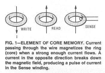
The basic core element is shown in Fig. 1. By passing conductors
through the center of the ferrite cores and passing a current
through the conductors in a set direction, a magnetic field is
created that magnetizes the core. A logic 1 has then been written
when the core is magnetized. (This process is similar to the one
used in making permanent magnets.)
The actual method of storing ones and zeros in a core is simple.
The basic core element is shown in Fig. 1. By passing conductors
through the center of the ferrite cores and passing a current
through the conductors in a set direction, a magnetic field is
created that magnetizes the core. A logic 1 has then been written
when the core is magnetized. (This process is similar to the one
used in making permanent magnets.)
Just the opposite is done to read or clear a core. A current sent through in the opposite direction, and consequently cancels any previous fields in thhe core. To read a core, an extra winding must be added: the sense winding.
When a core holds a logic 1 (is magnetized) the read current causes the magnetic flux to collapse and induce a voltage in the sense winding. If the core had held a logic 0 (been unmagnetized) no voltage would have been induced in the sense winding.
 This method is basically the idea, but is much too simple to
function in a real computer system. They type we shall be
concerned with is known as the 3-D, 4-wire. Three-D means a
three-dimensional array consisting of planes of cores arranged
in an X-Y format in which the total number of words is equal
to the number of cores per plane. (The number of bits per
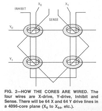
word is equal to the number of planes.) Four-wire signifies
that four wires pass through each core. They are: X Drive,
Y Drive, Inhibit lines and the Sense
windings. (See Fig. 2.)
This method is basically the idea, but is much too simple to
function in a real computer system. They type we shall be
concerned with is known as the 3-D, 4-wire. Three-D means a
three-dimensional array consisting of planes of cores arranged
in an X-Y format in which the total number of words is equal
to the number of cores per plane. (The number of bits per
word is equal to the number of planes.) Four-wire signifies
that four wires pass through each core. They are: X Drive,
Y Drive, Inhibit lines and the Sense
windings. (See Fig. 2.)
When a read/write (R/W) current passes through both X and Y drive lines, a core is magnetized (or demagnetized). If there is current on one drive line through one or many cores, these cores will not switch; it takes the sum of both X and Y currents to switch a core. The current on one line is known as the half current.
This half current is used to write a logic 0 into a core, with the help of the Inhibit lines. As a core is selected, as equal but opposite current on the Inhibit line cancels out the current on the Drive line parallel to it and this creates a half current. Remember, the drive lines only select the core to be written - it is the Inhibit lines that determine whether or not the core will be logic one or zero. During the read cycle, the drive currents are reversed and cause the magnetic field stored in the core to collapse and create a voltage on the Sense winding.
Core memory design
Memories of the core type are basically easy to design.
Circuitry is usually straigtforward, with simple timing methods.
All that one needs to service a core memory is an oscilloscope,
a VOM and sometimes a signal generator.
One can start a core system with a stack of core planes with the desired number of bits and words. Try to obtain the core stack parameters (current values for the Drive and Inhibit lines, etc.). Input/output designations for the core stack are also ncessary - the experimenter will be lost if he doesn't know what all the leads on the package are for.
Mount the core stack in a place relatively free from magnetic fields (away from motors, generators, solenoids and the like) and where cool air may circulate freely - continued use heats the Drive lines.
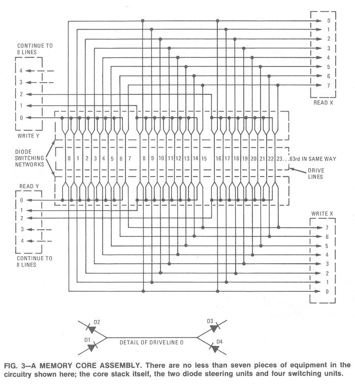
In the 4096-core unit partially illustrated in Fig. 3, there are 64 X-drive lines and 64 Y-drive lines (Fig. 3 shows only eight of one of these sets of lines.) One of each must be selected to switch a core. An Address unit supplies the information as to which drive lines are to be selected and in which mode (Read, Write, etc.). One of the simplest circuits incorporates a steering network to partially decode the address and steer the currents in the proper direction for read or write. Figure 3 shows that by selecting one X and one Y input any one of the 64 lines may be picked. The input lines to the diode decoders are numbered 0 to 7 X and Y. (Only one of those sets of lines is shown, to keep the circuit as simple as possible.) It is when one of eight X lines and one of eight Y lines are picked that a specific drive line is enabled.
Switching a core
It takes a specific amount of current to switch a core. This current
is switched on and off at the diode decoders desired by the X and Y
circuits. They are usually made up of single transistors biased
so that they turn on and off at long 1 and 0. Logic 1 is normally
4 volts, logic 0 is 1.4 volts TTL (transistor-transistor-logic) levels.
See Fig. 4.
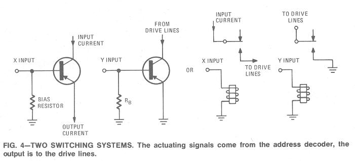
There are two sets of X and Y circuits. One sends current down the drive lines in one direction to write; the other in the opposite direction for the read operation. While transistors are most commonly used, one may use any desired technique: relays, switches, diodes, even vacuum tubes (all have been used) and need not incorporate the TTL methods described here.
So far the cores, mounted in their planes and assembled into stacks, the diode decoders and the switch and sink circuits have been discussed. How the cores receive their signals, how they are directed to certain cores in the stack, how they are called for and how information is restored to a core after it is destroyed are still to be learned.
R-E
Click here for the home page.
Last updated October 15, 2002.