Certus
Iridium Satellite Time and Location
Deorbiting
New Frequencies
Collision
Signals
Hardware
SIM
Test Mode
References
9602 AT Commands

|
TECHNICAL DETAILS
Certus
|
|
LINKS
|
| IRIDIUM CERTUS |
|
Iridium Next is expected to be significantly more capable than the legacy
system, which was originally designed by Motorola primarily for voice
communications in the 1990s. Since then, the company has squeezed more
capability out of the system by bundling and using channel compression
to keep up with demands for higher throughputs, operating at about 2.4
kilobytes per second.
The new Certus waveform will allow for more efficient channels and new antenna types that will increase bandwidth for handheld man-packable radios from 9.6 kilobytes per second to 88 kps. Large terminals, which are more likely to be used on vessels and land stations in the Arctic will range from 32 kps to 128 kps.
Iridium Certus terminals are being built by Cobham, L3 Communications, Rockwell-Collins, and Thales USA. New satellites orbit at 780 km with an 86.4° inclination and can support 1,100 simultaneous equivalent user channels (peak).
|
| IRIDIUM SATELLITE TIME AND LOCATION |
|
Iridium launched the Satellite Time and Location (STL) service in May 2016,
with primary technology partner Satelles (a division of iKare Corporation).
STL uses the narrowband paging channels of Iridium, a one-way transmission from the satellite with a high gain system. The STL signal is different from the wide band, lower gain two-way channel of the Iridium phone. The STL signal is 1,000 times stronger than GPS because it originates from the Iridium constellation of 66 satellites orbiting in a low earth orbit. It is also encrypted for high security, which greatly enhances resilient positioning, navigation and timing (PNT). The Iridium Constellation consists of 66 Low Earth Orbiting (LEO) satellites, primarily used for global communications. The satellites transmit in the L-Band at carrier frequencies in the range of 1616-1626.5 MHz, using Quadrature Phase Shift Keying (QPSK) with a symbol rate of 25,000 symbols per second. Transmission is frame based, with frame length of 90 ms. Iridium satellites travel at speeds of about 7500 m/s, resulting in variations of up to +/- 40 kHz from the nominal carrier frequency due to Doppler effects. Compared to GNSS signals, Iridium signals have much higher raw signal power (300 ~ 2400x) as seen by a receiver on Earth. Two main technical innovations are applied to the existing Iridium QPSK transmission scheme in order to facilitate precision measurements. First, the QPSK data at the beginning of a STL burst is manipulated to form a continuous wave (CW) marker, which can be used for burst detection and coarse measurement. Second, the remaining QPSK data in the burst is organized into pseudo-random sequences, reducing the effective information data rate while providing a mechanism for precise measurement via correlation with locally generated sequences. The processing gain associated with the sequence correlation operation also enhances the capability of the STL signal to penetrate buildings and other occlusions. STL bursts are transmitted once every 1.4 seconds on average. If coarse time is known, such as in the case of a receiver with a network connection, then precise time can be calculated by processing a single burst. Assuming the receiver can process a burst in < 0.6 seconds, precise time and frequency can typically be acquired using STL in under 2 seconds. The precise time and frequency information derived from a single STL burst can be used to assist weak-signal GNSS acquisitions. Since the STL signal is more robust than GNSS, precise assistance is provided to acquire GNSS signals as weak as -160 dBm, assuming that the STL and GNSS signals are attenuated similarly by path occlusions. |
| DEORBIT |
| Iridium completed deorbiting of 65 operational first-generation satellites on December 28, 2019, a process started in 2017 as Iridium NEXT began launching. A total of 95 satellites were launched between 1997 and 2002. Thirty of those malfunctioned and remain in low earth orbit. |
| LAUNCHES FOR IRIDIUM NEXT |
|
A SpaceX Falcon 9 rocket launched from Vandenberg Air Force Base lofted
the first ten Iridium Next satellites into orbit on January 14, 2017.
A SpaceX Falcon 9 rocket launched from Vandenburg Air Force Base lifted the second set of ten Iridium NEXT satellites on June 25, 2017. A SpaceX Falcon 9 rocket launched from Vandenburg Air Force Base lifted the third set of ten Iridium NEXT satellites in October 9, 2017. |
| NEW FREQUENCIES |
|
In October 2008, the FCC granted Iridium exclusive access to
1617.775 to 1618.725 MHz and shared access to 1618.725 to 1626.5 MHz,
based on a sharing plan set out in November 2007.
|
| COLLISION |
| In 2009, Iridium-33 collided with Cosmos-2251, a Russian satellite, resulting in more than a thousand pieces of debris. |
| SIGNALS |
|
Iridium uses a Frequency Division Multiple Access/Time Division
Multiple Access (FDMA/TDMA) scheme for communication with the
satellites using differentially-encoded QPSK modulation at 2400 bits per second.
The subscriber links are in L-band between 1616 and 1626.5 MHz. Feederlinks are in Ka band, with downlinks between 19.4 and 19.6 GHz and uplinks between 29.1 and 29.3 GHz. Intersatellite links are between 23.18 and 23.38 GHz at 25 Mbps. Ka band uplinks and cross-links are packetized TDMA, transmitted via QPSK with 1/2 rate convolutional forward error correction. Each satellite provides 48 individual spot beams, sharing 240 traffic channels with a frequency re-use pattern.
Voice
Channels
Frequency access is 41.667 kHz
Simplex Frequencies
Modulation
TDMA Frame
Data Bursts The uplink and downlink traffic channels use identical burst structures.
All data is transmitted at 50 kbps, so a 8.28 ms frame transfers 414 bits. A 2400 bps traffic channel uses one Uplink and one Downlink per frame
Paging From the FCC Order and Authorization (DA 96-1789). [MSC is Motorola Satellite Communications, Inc.]
Enhanced ringing and paging services. MSC requests explicit authorization for the IRIDIUM System to provide enhanced ringing and paging services, in addition to the kinds of MSS service that it originally proposed to provide. The enhancement would enable users to receive ringing and paging messages during heavier atmospheric fading conditions and in buildings where attenuation is greater, according to MSC. One-way "ring alert" channels at 1626.270833 MHz would be used to alert subscribers with special receive-only mobile earth terminals to the presence of incoming paging calls. Paging messages would be transmitted to the receive-only terminals at 1626.437500, 1626.395833, 1626.145833, or 1626.104167 MHz. Their duration would not exceed 20.32 milliseconds. The transmit power for the ring alert channel would be somewhat higher than the power used for a voice/data channel, so as to enable the mobile earth terminals to receive ring alerts even when their antennas are stowed, but spurious- emission performance would be better than that of the two-way channels on the system when fully loaded. MSC therefore contends that the addition of these services would not increase interference levels or complicate satellite-system coordination. No one else filed comments on this proposal.
Acquisition
Ring Alert The Iridium Ring Alert broadcast channel operates at 1626.270 MHz and is an unencrypted downlink-only channel used to send messages to individual subscriber units. These messages contain the satellite identifier, beam identifier, the latitude and longitude of the satellite location at ground level (derived from a proprietary algorithm), satellite altitude. Each beam transmits a Ring Alert message every 4.32 seconds. Since each satellite has 48 beams, a subscriber unit will receive a generic Ring Alert message every 90 milliseconds (4,320 ms /48 beams). Short Burst Data (SBD)
At the output of the BCH decoding process, there are ten, 20-bit words (one header word, eight data words and one CRC word) that make up one SBD PDU being fed to the CRC-16 decoding process.
|
| HARDWARE |
|
| Emission Designator |
|
The pertinent emission designator for the mobile satellite phone is 41K7Q7W.
Bandwidth is primarily determined by a 96 tap FIR filter used to filter I and Q channel modulating signals and is consistent with a necessary bandwidth specification of 41.667 kHz. Converting this result yields 41K7.
a. First Symbol - Type of Modulation of the main carrier.
b. Second Symbol - nature of signal(s) modulating the main carrier.
This corresponds to symbol 7, derived from two channels "containing quantized or digital information" modulated in-phase and quadrature modulated.
c. Third Symbol - Type of information to be transmitted.
This corresponds to W, defined as "combinations of above" which would be the combination of the symbol D, "Data transmission, telemetry, telecommand", and symbol E, "Telephony (including sound broadcasting)". The resulting complete emission designator is then 41K7Q7W. |
| IRIDIUM 9501 PAGER |
|
FCC ID: E969898
Dimensions: 77w x 72.3h x 22.5d mm (3.03w x 2.85h x .88d in) Motorola Part Numbers
|
| Channel Plan |
|
The frequency range of the equipment is in the band of 1616 MHz to 1626 MHz.
Band is channelized. Center frequency determined by:
A 12-frequency access band is reserved for the simplex (ring alert and messaging) channels. These channels are located in a globally allocated 500 kHz band between 1626.0 MHz and 1626.5 MHz. These frequency accesses are only used for downlink signals and they are the only L-band frequencies that may be transmitted during the simplex time-slot.
Frequency Stability: +/- 0.00015 % (1.5 ppm) This equipment uses Automatic Frequency Control (AFC) to lock within +/- 600 Hz of the received frequency from the Space Vehicle (SV). The mobile performs all frequency pre-correction for Doppler shifts, up to +/- 37.5 kHz. The system is designed to be tolerant of these frequency offsets. Radio Frequency Output Power ranges from 0.1 to 0.6 Watts. The mobile maximum output power is achieved under closed loop control with the SV network. The mobile power will respond to commands from the SV network to change power levels as defined in the specifications. RF Power Output: Variable range from 0.1 to 0.6 Watts (by control of satellite network via closed loop power control). The transmitter duty cycle allows for bursted transmission every 8.28 ms out of 90 ms, or 9.2%, at a rate of 50 kbps, or 25 k symbols/sec. Modulation is DEQPSK (Differentially Encoded Quadrature Phase Shift Keying).
|
| ACCESS AND PRIORITY |
|
Each satellite beam broadcasts which Acquisition Classes are allowed
to acquire satellite resource on that beam. Only SDUs with the
proper Acquisition Class (AC) are allowed to start the acquisition
process. Acquisition Class ranges from 0-15. Default non-safety Iridium
terminals use an Acquisition Class in the range of 0-9.
Acquisition Class is mainly used for satellite load shedding. In a satellite beam with heavy traffic load, certain Acquisition Classes (e.g., AC0-9) will be shut down to prohibit further traffic load on the satellite.
0-9: Regular Subscribers The Acquisition Class affects how calls initially gain access to the satellite constellation. The Iridium Satellite Network allows for four levels of priority. Each satellite has priority queuing for both channel assignment of new calls and handoff order of in-progress calls. High priority calls, taking precedence, are queued before low priority calls. Currently both the Acquisition Class and Priority Class are encoded on a SIM card; hence the Acquisition Class and Priority Class are associated with a SIM card and an SDU that uses that SIM card. |
| SIM |
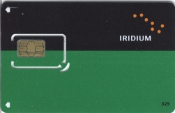 Iridium devices that are capable of completing circuit-switched calls use a
Subscriber Identity Module (SIM), a type of
smartcard.
Iridium devices that are capable of completing circuit-switched calls use a
Subscriber Identity Module (SIM), a type of
smartcard.
|
| IRIDIUM-Specific SIM Files |
|
Besides the standard SIM files for a GSM (Global System for Mobiles) network, Iridium SIMs also contain
an additional Directory File (DF) called DFIRIDIUM with an identifier of 5F30.
[MF/DF] RFU: 00 00
  Free Memory: 00 00
  File ID:     5F 30 (DF-IRIDIUM)
  File Type:   02 (Directory File)
  RFU:         00 00 00 00 00
  Length Following: 0D
  File characteristics:    13
    Clock stop:     Allowed, no preferred level
    Required speed: 13/4
    CHV:            Enabled
  Child DFs:               00
  Child EFs:               07
  CHVs, Unblock CHVs, etc: 04
  RFU:                     00
  CHV1 Status:             83 (Initialized, 3 remaining)
  Unblock CHV1 Status:     8A (Initialized, 10 remaining)
  CHV2 Status:             83 (Initialized, 3 remaining)
  Unblock CHV2 Status:     8A (Initialized, 10 remaining)
  RFU:                     00
This DF contains seven Elementary Files. I do not have documentation for these files:
  4F20 (16 bytes): FF 15 FC AF 05 2C 0A 4C FE 44 EB DC 1B 00 08 31
  4F21 Record 1 (14 bytes): FF FF FF FF FF FF FF FF FF FF FF FF FF FF
  4F23 (3 bytes): 13 F0 10
  4F24 Record 1 (4 bytes): 11 F2 FF 08
  4F24 Record 2 (4 bytes): 19 F1 FF 08
  4F24 Record 3 (4 bytes): FF FF FF FF
  4F24 Record 4 (4 bytes): FF FF FF FF
  4F25 (1 byte): 05
  4F26 (1 byte): 05
  4F27 (1 byte): 05
|
| Authentication |
|
The Iridium authentication process is adapted without change directly from the GSM specifications.
The GSM encryption algorithm A3 is executed on SIM card to generate Signed Result (SRES) response based on the following inputs:
The Iridium SIM supports the standard GSM authentication algorithm (known as A3) and the ciphering key generating algorithm (known as A8). They are combined in a single SIM instruction called "RUN GSM ALGORITHM". Example:
To SIM (21): A0 88 00 00 10 00 00 00 00 00 00 00 00 00 00 00 00 00 00 00 00 (The "RUN GSM ALGORITHM" and 16 bytes representing RAND)
It is interesting to note that the last ten bits of Kc are always zero, reducing the effective keyspace from 64 to 54 bits. Terrestrial GSM has long been limited, as summarized in a document (Tdoc SMG P-99-011) from an ETSI/TC/SMG meeting in Italy in 1998: The GSM encryption uses in principle a 64 bit key. However at introduction of GSM it was decided to limit the effective key size to 54 bits. This should have been realised by the SIM and the Authentication Centre (AuC) both forcing 10 specific bits of the encryption key to zero.
|
| KEYPAD COMMANDS |
|
| TEST MODE |
|
The original Motorola 9500 handset supports a test mode using a special test SIM card.
There is some overlap between the test commands used on Motorola GSM cellular telephones.
I would be interested in receiving a list of all the available test mode commands, and/or the entire service manual for an Iridium phone. With the special SIM card in place, press and hold the [#] key for more than three seconds.
27 is a transmit test.
xxx = channel number Transmit random data (z = 1) on channel 001 at maximum power (00): 27001001# Transmit a tone (z = 0) on channel 240 at minimum power (08): 27240080# Stop transmitting: 27#
One command that is different is the Static Traffic Channel command ( #29xxyyzabc# ).
|
| REFERENCES |
|
| 9602 AT COMMANDS |
|
The 9602 is a Short Burst Data (SBD) module that provides packetized data connectivity.
It communicates with an external device via a serial connection
and uses "AT" commands.
Default serial communication parameters: 9600 baud, no parity, 8 data bits, 1 stop bit.
|