|
NASA Tech Briefs Article
GPS Receiver RF Front-End Enables Use of a Laptop PC for Soft Baseband Processing
Friday, 24 August 2007
Software techniques for use in the global positioning system (GPS)1,2 have
recently captured the growing interest of communication and navigation
engineers. Thanks to very-largescale integration (VLSI) development,
powerful CPUs and DSPs are now capable of detecting and decoding GPS
signals in real time using software. The resulting software-based
GPS receivers offer considerable flexibility in modifying settings to
accommodate new applications without hardware redesign, using the same
board design for different frequency plans, and implementing future
upgrades.
The CPU inside most of today's laptop computers has plenty of performance
to meet the real-time decoding needs. By using a chip like the MAX2741
GPS receiver RF front-end, a simple USB dongle or PCIexpress minicard
can be used to add low-cost GPS capability to a laptop PC, by letting
the PC execute the baseband decoding in software, eliminating the cost
of the baseband ASIC typically required in standalone GPS systems.
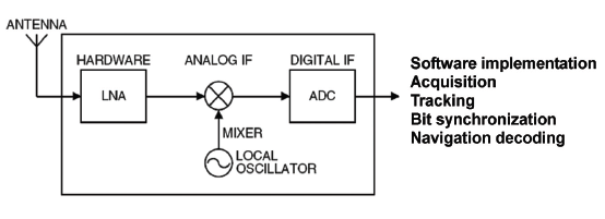 Figure 1. In a software GPS receiver, the captured RF signal must be
amplified, mixed down in frequency, and then digitized.
The RF front-end of a software-based GPS receiver first amplifies the weak
incoming signal with a low-noise amplifier (LNA), and then downconverts
the signal to a low intermediate frequency (IF) of approximately 4 MHz
(Figure 1). This downconversion is accomplished by mixing the input RF
signal with the local oscillator signal using one or two mixers. The
resulting analog IF signal is converted to a digital IF signal by the
analog-todigital converter (ADC).
Figure 1. In a software GPS receiver, the captured RF signal must be
amplified, mixed down in frequency, and then digitized.
The RF front-end of a software-based GPS receiver first amplifies the weak
incoming signal with a low-noise amplifier (LNA), and then downconverts
the signal to a low intermediate frequency (IF) of approximately 4 MHz
(Figure 1). This downconversion is accomplished by mixing the input RF
signal with the local oscillator signal using one or two mixers. The
resulting analog IF signal is converted to a digital IF signal by the
analog-todigital converter (ADC).
All those functions - LNA, mixer, and ADC - have been integrated
into the MAX2741, thus significantly reducing the development time for
applications. A two-stage receiver amplifies the incident 1575.42-MHz GPS
signal, downconverts it to a first IF of 37.38 MHz, further amplifies
it, and then downconverts to a second IF of 3.78 MHz. An internal 2-
or 3-bit ADC (selectable as a 1-bit sign with a 1- or 2-bit magnitude)
samples the second IF and outputs a digitized signal to the baseband
processor. The integrated frequency synthesizer enables flexible frequency
planning, allowing the same board to implement many popular reference
frequencies between 2 and 26 MHz with just a change of settings. The
integrated reference oscillator enables operation with either a crystal
or a temperature-compensated crystal oscillator (TCXO).
A simple USB dongle reference design based on the MAX2741 and a Cypress
Semiconductor USB controller operates from a 24-MHz crystal reference
(to match the clock required by the USB controller). It also employs
two MAX8510 LDOs to regulate the DC supply. A 3-wire (SPI) digital bus
is used to program the registers of the MAX2741. This reference design
allows a hardwired connection of the active antenna onto the PCB, thus
integrating it into the design. It also includes additional circuitry
to turn off the antenna during shutdown mode for USB compliance. The
MAX2741 also includes an integrated synthesizer that allows a single
board design to be employed for reference frequencies up to 26 MHz. The
integrated reference oscillator allows either TCXO or crystal operation.
Before examining the design of the USB or PCIe hardware, let's review a
little of the basic theory for software GPS receivers. For the decoding of
navigation messages and position calculations, the interested reader can
refer to James Bao-Yen Tsui's book, Fundamentals of Global Positioning
System Receivers: A Software Approach.
GPS Basics
A GPS system consists of 24 space satellites or space vehicles (each
identified by a unique PRN code), a ground-control station, and user
equipment (receivers). For civilian GPS applications, the satellites
communicate over the L1 band located at 1.57542 GHz. A GPS receiver
requires line-of-sight .visibility. of at least four satellites to
establish a reliable position. Acquisition and tracking of the signals
is very complex, because each one varies with time as well as receiver
location.
Traditional GPS receivers implement acquisition, tracking, and
bit-synchronization operations in an ASIC, but a software GPS receiver
provides flexibility by implementing those blocks in software rather
than hardware. By simplifying the hardware architecture, software makes
the receiver smaller, cheaper, and more power-efficient. You can write
the software in C/C++, MATLAB®, and other languages, and port it into
all operating systems (embedded OS, PC, Linux, and DSP platforms). Thus,
software GPS receivers offer the greatest flexibility for mobile handsets,
PDAs, and similar applications.
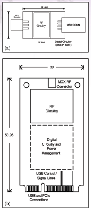 Figure 2. Typical adapter configurations for the USB dongle (a), and
the PCIe minicard (b) showthe simple, low bill of materials design for
either option.
For laptop computers, designers can opt to design either a USB
"dongle" that can work with any laptop with USB ports, or
for newer laptops that have a PCIexpress minicard connector, they can
put the RF front-end on the PCIe minicard and embed the card in the PC
(Figure 2a, b). The PCIe minicard interface includes a USB port, so the
design of the front-end adapter is similar for both USB and the PCIe
minicards. The main difference is in some of the powermanagement logic
required for the PCIe support and to deal with the different DC voltages
(3.3-V for PCIe and 5-V for external USB ports).
Figure 2. Typical adapter configurations for the USB dongle (a), and
the PCIe minicard (b) showthe simple, low bill of materials design for
either option.
For laptop computers, designers can opt to design either a USB
"dongle" that can work with any laptop with USB ports, or
for newer laptops that have a PCIexpress minicard connector, they can
put the RF front-end on the PCIe minicard and embed the card in the PC
(Figure 2a, b). The PCIe minicard interface includes a USB port, so the
design of the front-end adapter is similar for both USB and the PCIe
minicards. The main difference is in some of the powermanagement logic
required for the PCIe support and to deal with the different DC voltages
(3.3-V for PCIe and 5-V for external USB ports).
The USB dongle solution can be simple, with just the MAX2741, a counter,
and the USB interface controller needed to capture the signal convert
it to digital and send it to the host PC. Software running on the host
PC then performs all the baseband functions and displays the location
on the PC screen.
This article will only examine the civilian GPS signal on the well-known
L1 band located at 1.57542 GHz. The GPS system is actually a simple
spreadspectrum communication system4. First, the 50-bps navigation
message is repeated 20 times to produce a 1,000- bps bit stream. The
repeated signal is then spread by a unique C/A code with a length of
1,023 chips (a chip is the rate at which the pseudorandom noise code is
applied). The result is a baseband signal of 1.023 megabits per second
(Mbps). Hence, the 43-dB processing gain (G) of the GPS system permits
it to resolve a signal well below the thermal noise level.
Each satellite is assigned a unique C/A code, also called a
gold code5. Because the gold code exhibits excellent auto- and
cross-correlation properties, it is widely used in CDMA communication
systems such as WCDMA, cdma2000®, and others. The baseband signal is
modulated with binary phase-shift keying (BPSK), and upconverted to the
L1 band for transmission.
Acquiring the Signal
Because GPS is a CDMA communications system, the receiver must synchronize
the pseudorandom noise (PRN) code as a prerequisite to demodulating
the data. Code synchronization is usually achieved in two steps: code
acquisition for the coarse-code alignment, and code-phase tracking for
the fine alignment6. More explicitly, a GPS receiver must first determine
whether it has lineof- sight visibility to certain satellites. As we know,
each satellite is distinguished by a unique C/A code. When the satellite
is visible, acquisition determines the signal.s frequency and code phase,
which in turn establishes the corresponding demodulation parameters. The
received-signal frequency varies due to the Doppler effect7, which causes
the frequency to deviate from its nominal value by 5 kHz to 10 kHz,
depending on the speed of the satellite with respect to the receiver.
In the receiver, the GPS signal is first downconverted to in-phase
and quadrature (I and Q) components. A pair of IQ correlators then
correlates the I and Q baseband signals with the locally generated
PRN sequence. After integrating over the duration of one bit, the I-Q
correlator outputs are summed to provide an output-decision variable.
Whenever the decision variable exceeds a certain threshold value,
the system assumes the corresponding acquisition was successful and
proceeds to the tracking mode. Otherwise, the relative phase of the
locally generated PRN sequence and the oscillator frequency are adjusted
to update the decision variable, and the above process is repeated. The
simple logic structure of the serialsearch method makes it feasible for
implementation in an ASIC, but for software implementations it is not
practical because the search space is huge.
Assuming the system tolerates a 500- Hz carrier-frequency offset
and the Doppler frequency is 10 kHz, the search space for a software
implementation is roughly 2 × (10,000/500) × 1023 = 40,920. Obviously,
a serial-search acquisition would be difficult in software.
Another acquisition method, called frequency-domain parallel code-phase
acquisition, is less complex to implement with software. In this method,
the Doppler-frequency and code-phase searches are combined into one
search, which, after an FFT transform of the PRN code, reflects all
code-phase information into the frequency domain. We then need only to
search the space over the Doppler-frequency offset, thereby implementing
a fast and effective software search.
The system implements this by first multiplying the incoming signal with
the locally generated sine and cosine carrier waves respectively (the I
and Q signal components). The I and Q components are then combined as
a complex input to an FFT block. The result of this Fourier transform
is multiplied with the conjugate of a PRN code's FFT transform (the
PRN generator generates a code with zero-code phase). In practice,
the FFT operation and generation of PRN code can be tabulated to reduce
computation complexity.
Finally, the product of the incoming signal and local code, which represents the correction between the incoming and carrier frequencies, is applied to an inverse Fourier transform whose squared output feeds back to the decision logic. The FFT-based frequency domain has proven to be a low consumer of computation. For the example mentioned earlier, the complexity of acquisition is roughly 20,000/500 = 40 FFT operations.
Thus, the serial-search method has the simple logic and control architecture necessary for a convenient ASIC implementation. The huge search space, however, imposes complexity on the software algorithm. The serial-search method is therefore not a good choice for software GPS receivers. In contrast, the low complexity of the parallel-code acquisition method makes it ideal for the software implementation. Its logic architecture, however, is far more complex than that of the serial-search method, making it difficult to implement in an ASIC.
Tracking Refines Alignment
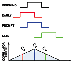 Figure 3. The DLL circuit multiplies the incoming signal by three local
replicas of the PRN code (positioned in time at ± 0.5 chip),which
represent early, prompt, and late arrivals with respect to theincoming
signal. The one with the highest correlation value is then selected
and retained.
Figure 3. The DLL circuit multiplies the incoming signal by three local
replicas of the PRN code (positioned in time at ± 0.5 chip),which
represent early, prompt, and late arrivals with respect to theincoming
signal. The one with the highest correlation value is then selected
and retained.
Acquisition establishes a coarse alignment of the GPS signal's frequency
and code-phase parameters. The purpose of tracking, therefore, is to
refine this alignment so the system can demodulate the data with exact
code-phase and frequency information. Tracking includes code-phase
tracking and carrier-frequency tracking.
The DLL circuit multiplies the incoming signal by three local replicas of
the PRN code (positioned in time at ±0.5 chip), which represent early,
prompt, and late arrivals with respect to the incoming signal. After
integration, each of these signals represents a correlation between the
incoming signal and a local replica. The one with the highest correlation
value is then selected and retained (Figure 3). Carrier-frequency tracking
is carried out by a phase-lock loop (PLL) or Costas loop8. The purpurpose
of carrier tracking is to tune the locally generated frequency to the
exact frequency of the incoming signal.
After acquisition and tracking have established the initial
synchronization, the system can decode the navigation bits. Data
demodulation begins by despreading the 1.023-Mbps input signal to a
1,000-bps bit stream. Bit synchronization is then invoked to recover the
50-bps information from the 1,000-bps stream. For bit synchronization,
we first need to identify the beginning of a bit in time. This is
accomplished by finding the zero-crossing edge (at 0V), which indicates
the beginning of a bit. When that edge is known, we can partition the
1,000-bps input stream at 20-ms intervals, knowing that the duration of
a navigation data message (50 bits) is 20 ms. Finally, the bit samples
in a 20-ms interval are summed and averaged to decode the navigation data.
The software that runs on the PC is the swGPS. Spot Version 2 from
NXP's Software division. It can turn a notebook PC into a powerful
location device, supporting navigation and a wealth of location- based
services. The GPS front-end streams digitized IF data into the notebook
via the industry-standard USB 2.0 interface. The Spot software uses
the input to calculate a position fix and subsequently, to perform
tracking. The code footprint on the host PC is about 750 kbytes and
the software needs about 27 Mbytes of workspace when fed by a 12 Mbit/s
GPS front end data stream. (For more information on the software, go to
www.software.nxp.com or www.swgps.com.)
[NOTE: The web links mentioned in this article are out of date.]
A virtual COM port created by the software allows the software to link to
a wealth of existing navigation and location applications. The software
output interface conforms to NMEA 0183 and the application can run on
Microsoft.s Windows XP and Vista operating systems. Additionally, the
software can handle all available assistance data, whether supplied via
industrystandard protocols or proprietary customer interfaces. When the
software runs on a 1-GHz Pentium M system, the average processor load
when tracking is 13%; when run on a Pentium Core Duo processor running
at 2.18 GHz, the processor load is just 4%, both when performing updates
every second.
Software GPS techniques provide a high level of flexibility and simplicity
for many potential applications. To support these possibilities, the
MAX2741 RF front-end provides flexibility in frequency planning for
software GPS receivers and traditional hardware implementations as
well. Of course, every solution has its pros and cons . software GPS
receivers require a high-performance processor and moderate amounts
of memory.
This article was written by David Weber, Strategic Applications Engineer,
at Maxim Integrated Products Inc. in Sunnyvale, CA.
(MATLAB is a
registered trademark of The MathWorks; cdma2000 is a registered trademark
of the Telecommunications Industry Association.)
References
[1] E. Kaplan. Understanding GPS: Principles and Applications. 2nd ed. Artech House Publishers, 1996.
[2] J. Bao-Yen Tsui. Fundamentals of Global Positioning System Receivers: A Software Approach. 2nd ed. John Wiley & Sons Inc., 2004.
[3] Ibid. [4] A. Viterbi. Principles of Spread Spectrum Communications. Addison Wesley Longman Publishing Co., Inc., 1995.
[5] R. Gold, Co-optimal binary sequences for spread spectrum multiplexing, IEEE Transactions on Information Theory. Vol. IT-13. October 1967. pp. 619.621.
[6] R. E. Ziemer and R. L. Peterson. Digital Communications and Spread Spectrum Systems. New York: Macmillan Publishing Company, 1985.
[7] J. G. Proakis. Digital Communications. 4th ed. Mc-Graw Hill College, 2000.
[8] Ibid.
|